ENTRON Controls, LLC. • 700120S • Page 29
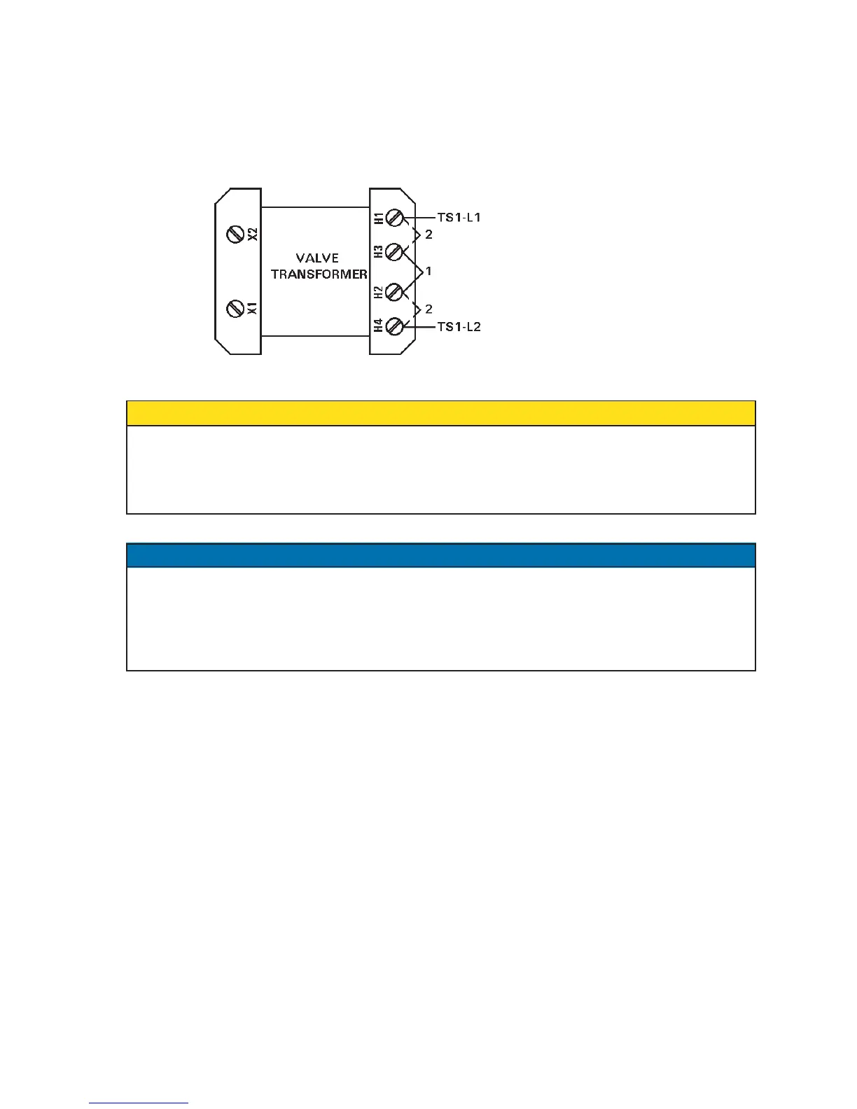
3. Valve Transformer: Jumpers on the valve transformer H1, H3, H2, and H4 must be
configured to match the line voltage (see Figure 4-2). The standard Valve Transformer
included with the EN1000/EN1001 (either 50 VA or 150 VA) is configured for 240 VAC or
480 VAC input; for 380 or 575 VAC operation, consult the factory.
Figure 4-2. Valve Transformer jumpers settings
When external valve power is used (24-240 VAC), Valve Transformer MUST be
disconnected at TS1-VL1 and TS1-VL2.
Caution must be used to properly insulate the wires from X1 and X2 leads after
removing them from TS1.
Whether valve power is supplied by the Valve Transformer or by an external valve power
supply, the maximum current that can be switched by the solid state relays on the Firing
Board is maximum 1 A per valve. If more current is desired, the valve circuit should be wired
to an external relay having a suitable contact rating to switch the desired valve. For more
information, refer to Wiring Diagram shipped with the control.
JUMPER SETTINGS EXAMPLES:
240 Volt Operation Jumpers
Terminal Strip TS1:
• Jumper H1/H3 and H2/H4
• Jumper CTH1/CTH3 and CTH2/CTH4
Valve Transformer:
• Jumper H1/H3 and H2/H4
480 Volt Operation Jumpers
Terminal Strip TS1:
• Jumper H3/H2
• Jumper CTH3/CTH2
Valve Transformer:
• Jumper H3/H2
4.1 OPERATING VOLTAGE (cont.)
CAUTION
NOTICE
USE JUMPER #1 FOR 480 VAC
USE JUMPERS #2 FOR 240 VAC

 Loading...
