ENTRON Controls, LLC. • 700120S • Page 39
L1 and H1 will radiate electromagnetic
spikes onto the parallel wires bundled
with it. Initiation wires are low voltage
and are most vulnerable to
electromagnetic spikes. Also, a short
within this bundle could cause severe
damage. CAUTION: NEVER connect
Terminal Strip GND to earth ground.
BETTER example is shown in Figure 4-11.
Wires are routed parallel to each other but in
separate grounded conduits. Conduits isolate
vulnerable wires and reduce noise, but often,
when conduits are running parallel, wires will
have some unprotected travel distance inside
cabinet. This could couple some
electromagnetic spikes onto more vulnerable
low voltage circuits.
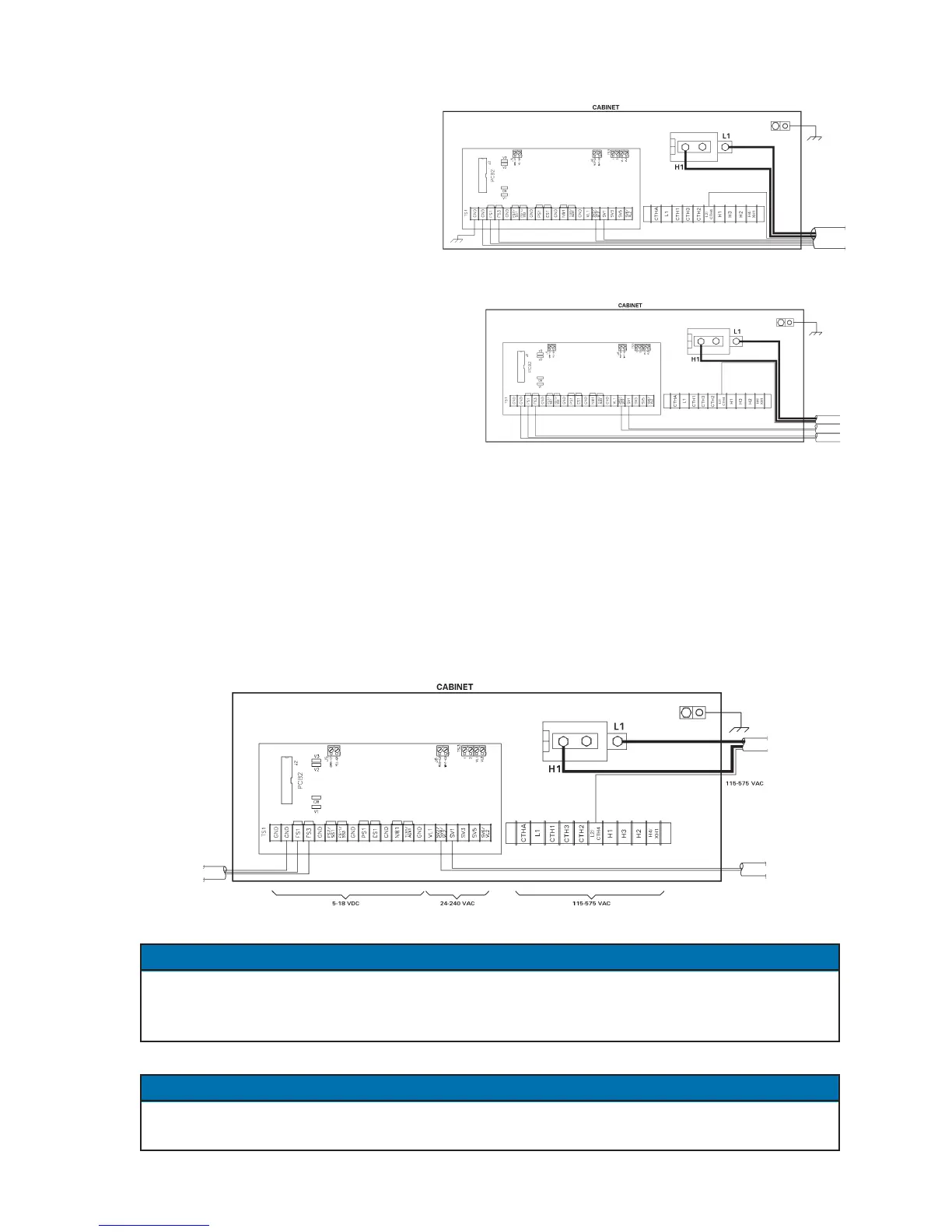
Use BEST wiring method shown in Figure 4-12 to minimize introduction of induced electrical
transient spikes that cause corrupt data to be stored in control’s microprocessor. Note that all
low voltage initiation wires have been physically isolated from any high voltage wiring. The
routing method used in our example is not possible in all applications, but should be considered
the best possible. It would be ideal to route and exit low voltage terminals (5-18 VDC) at least
6" or more or at opposite end of cabinet from higher voltage terminals (24-240 VAC) and (115-
575 VAC).
Figure 4-12. Recommended routing of low and high voltage wires
The GND designations on Terminal Strip TS1 are commons only (nominally at ground
potential). These points should never be grounded externally. However, control cabinet must
be properly grounded using ground lug on inside of cabinet.
Avoid routing high and low voltage wires parallel to each other to eliminate coupling
adjacent signals which may cause irregular operation.
Figure 4-10. Wrong routing of low and high voltage wires
4.6 NON-VOLATILE MEMORY ERROR (cont.)
NOTICE
NOTICE
Figure 4-11.
Better routing of low and high voltage wires

 Loading...
