Page 86 • 700120S • ENTRON Controls, LLC.
Schedule 20 is used to show how DOWNSLOPE and WELD parts of the sequence are
programmed in a single schedule. The bottom current by default is equal to one quarter of
PERCENT CURRENT. In this example, starting current is 80%; bottom current is: 80%/4 =
20%; and PERCENT CURRENT increment is: (80% - 20%)/10 = 6%.
Schedules 21 and 22 are used to show how two CHAINED schedules can be used to program
WELD and DOWNSLOPE parts of the weld sequence with any desired values for bottom
current of last DOWNSLOPE pulse. The bottom current is 10%, and PERCENT CURRENT
increment is: (75% - 15%)/15 = 4%.
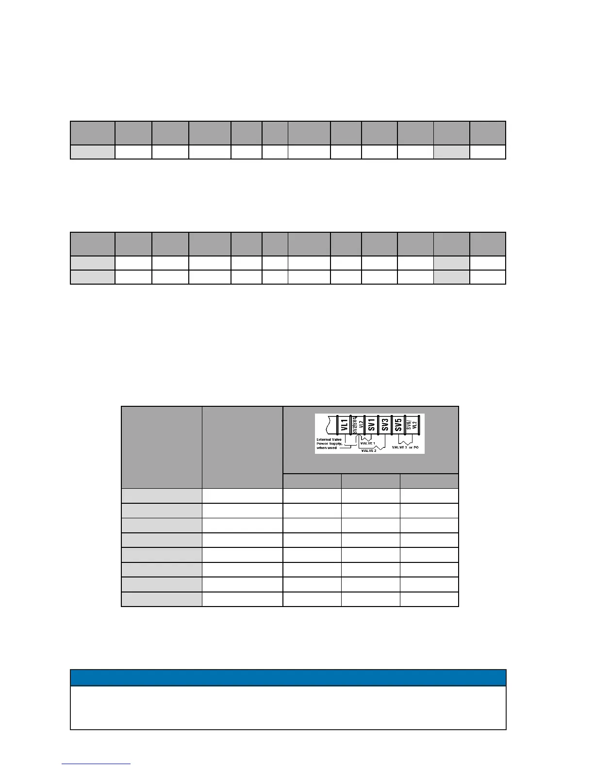
6.4 VALVE MODES
Each programmed schedule can have any one of the three valve outputs (or none) enabled
during its schedule. The three solenoid valves are activated based on the VALVE MODE
programmed as shown in Table 6-2.
Table 6-2. VALVE MODES and Valve Outputs
When in PROGRAM mode and selection of VALVE MODE is being made, the VALVE indicator
LEDs will indicate the selected valve(s). The valve output(s) will not be energized while in
PROGRAM mode.
The VALVE MODES indicated within the valve selection chart may differ with the use of
PROCESS OUTPUTS. Refer to Section 5.4.7 of this manual for further information on the
use of Valve 3 as a PROCESS OUTPUT indicator.
6.3.3 DOWNSLOPE – SLOPE MODE=
0202
0202
02 (cont.)
NOTICE
SCHEDULE SQUEEZE
WELD/
HEAT
PERCENT
CURRENT
HOLD OFF IMPULSES COOL
VALVE
MODE
CYCLE
MODE
SLOPE
MODE
SLOPE
COUNT
20 10 25 80 20 00 01 00 01 00 02 10
SCHEDULE SQUEEZE
WELD/
HEAT
PERCENT
CURRENT
HOLD OFF IMPULSES COOL
VALVE
MODE
CYCLE
MODE
SLOPE
MODE
SLOPE
COUNT
21 10 20 75 00 00 01 00 01 02 02 15
22 00 00 15 20 00 01 00 01 00 00 00
TS1-SV5 TS1-SV3 TS1-SV1
00 0 0 0
01 0 0 1 X
02 0 1 0 X
03 0 1 1 X X
04 1 0 0 X
05 1 0 1 X X
06 1 1 0 X X
07 1 1 1 X X X
VALVE MODE
(binary)
VALVE LEDs:
3, 2, 1
Valve Outputs

 Loading...
