ENTRON Controls, LLC. • 700120S • Page 15
2.3 OTHER PROGRAMMABLE SEQUENCE PARAMETERS
IMPULSES (13) – The number of heat IMPULSES that will occur in a schedule.
PERCENT CURRENT (9) – The percentage of conduction time provided to the welding
transformer primary from 0 to 99%, adjustable in 1% steps. This parameter is also used to set
HIGH and LOW limits in CONSTANT CURRENT mode (see Section 8.3.2).
SLOPE MODE (17) – Determines direction of the ramp with respect to programmed weld
PERCENT CURRENT. See Section 6.3 for detailed information on SLOPE MODE functions.
Table 2-1. SLOPE MODES
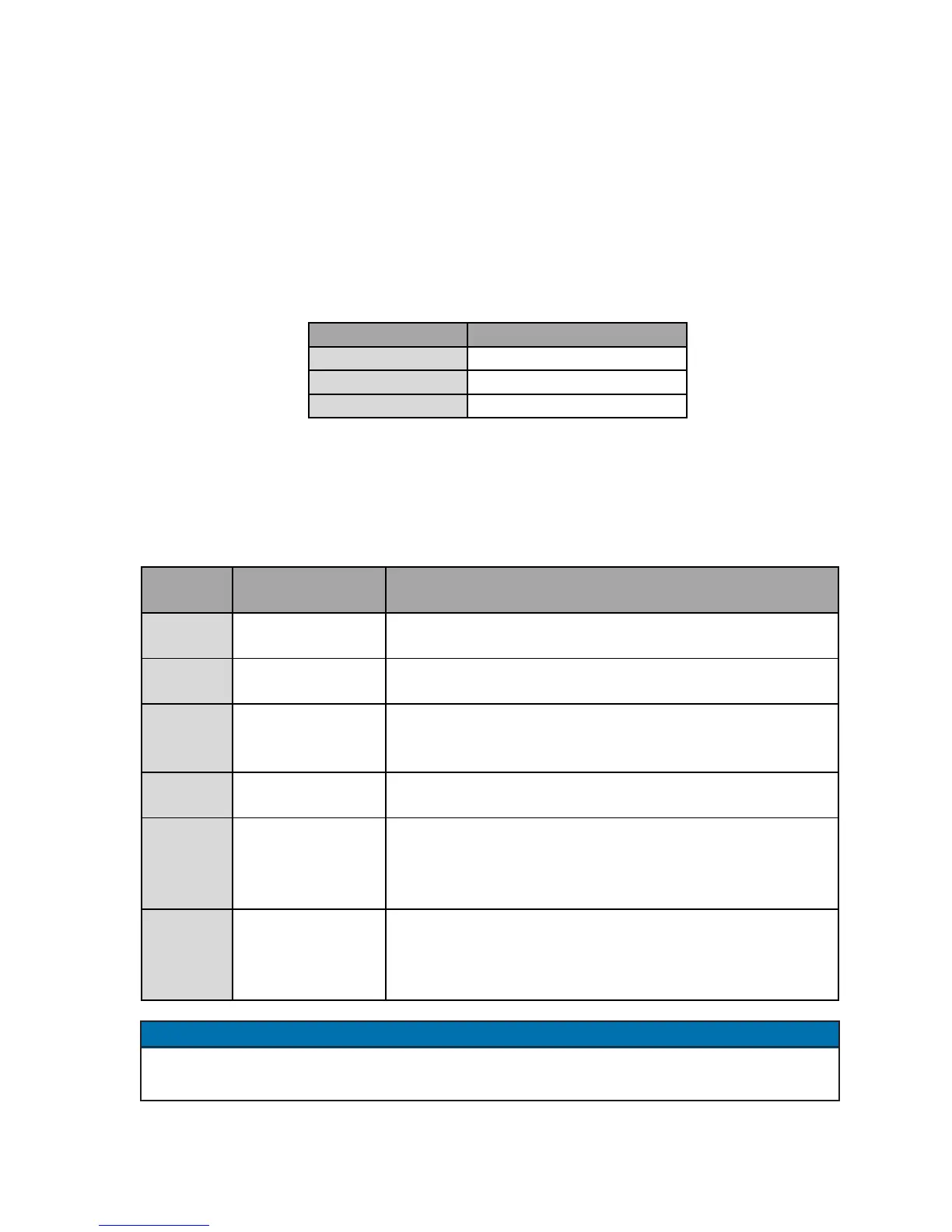
CYCLE MODE (16) – The manner in which the control performs schedules is determined by
the code programmed into this function as described in Table 2-2. See Section 6.2 for detailed
information on CYCLE MODE functions.
Table 2-2. CYCLE MODES
The CYCLE MODE and SLOPE MODE function codes are printed on the Control Panel,
adjacent to the ENTER push button, for operator convenience.
NOTICE
SLOPE MODE Description
00
NO SLOPE
01
UPSLOPE
02
DOWNSLOPE
CYCLE
MODE
MODE
Description
00 NON-REPEAT
The control can be initiated for only one sequence (see
Section 6.2.1)
01 REPEAT
After initiation, the control internally re-initiates as long as
the initiation switch is maintained closed (see Section 6.2.2)
02 CHAINED
Several schedules can be chained together so that several
consecutive schedules can be sequenced from one initiation
(see Section 6.2.3)
03 SUCCESSIVE
Several schedules can be sequenced successively upon
separate initiations (see Section 6.2.4)
04
CONDITIONAL
SUCCESSIVE
Valves remain active at the end of HOLD (this is indicated
by blinking HOLD indicator LED ) until control is re-
initiated and next schedule will be sequenced (see Section
6.2.5)
05 WAIT-HERE
After FS3 initiation, wait either in SQUEEZE or WELD-
COOL or HOLD part of the sequence until control is re-
initiated with FS7 or FS11 and schedule 10 or 20 will be
sequenced (see Section 6.2.6)

 Loading...
