ENTRON Controls, LLC. • 700120S • Page 57
5.4.4 AUTOMATIC VOLTAGE COMPENSATION AND MONITORING –
C.C.C.C.
C.C.C.C.
C.C.
In addition to the original AUTOMATIC VOLTAGE COMPENSATION (AVC), an additional
series of settings are available in the EN1000 or EN1001 Controls with PROM firmware
version 619016-002A or later. The new settings allow voltage monitoring, or compensation and
monitoring.
To program AUTOMATIC VOLTAGE COMPENSATION (AVC) or VOLTAGE
MONITORING (AVM):
1. Put the control in PROGRAM mode.
2. Click SELECT until the DATA display shows
EFEF
EFEF
EF.
3. Click the left SCHEDULE push button until the SCHEDULE display shows
C.C.C.C.
C.C.C.C.
C.C.
4. Use the DATA push buttons and the tables below to program the desired values.
5. Press ENTER.
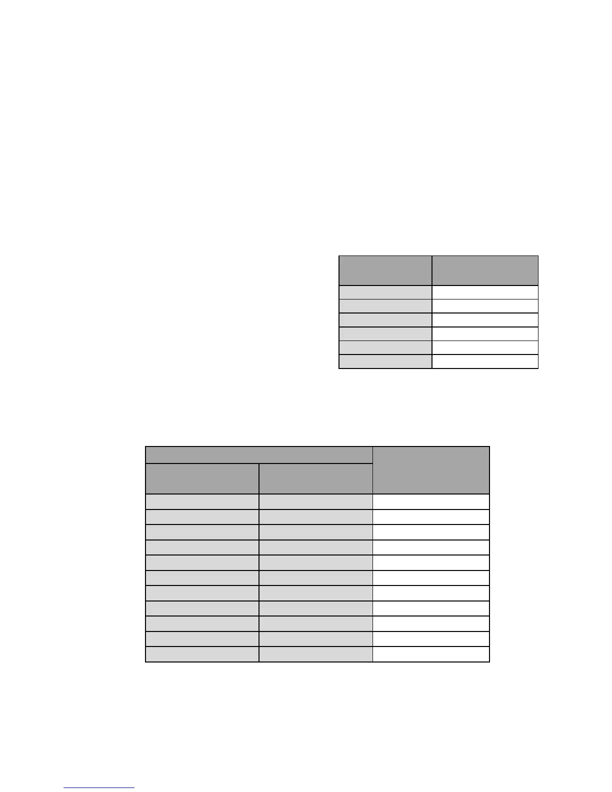
Original AVC settings are shown in Table 5-4.
These settings are available on all controls, but
they can be used only for compensation, not for
monitoring.
Additional AVC and AVM settings are shown in Table 5-5. These settings are available only on
controls with PROM firmware version 619016-002A or later.
Table 5-5. AVC parameter values
The AUTOMATIC VOLTAGE COMPENSATION uses a nominal set point value to determine
whether the line voltage is changing during idle periods (between welds). The AVC (
C.C.C.C.
C.C.C.C.
C.C.) values
must be set during a time in which the line voltage is at this nominal value. For example, if the
steady state line voltage is approximately 480 VAC, do not program
C.C.C.C.
C.C.C.C.
C.C. until the line voltage is
as close to 480 VAC as possible.
Table 5-4. Original AVC values
AVC parameter
Line Voltage
in VAC
00
AVC disabled
01 110
02 230
03 380
04 460
05 575
MONITORING &
COMPENSATION
MONITORING
ONLY
10 11 +/- 3%
12 13 +/- 5%
14 15 +/- 10%
16 17 +/- 15%
18 19 +/- 20%
20 21 +/- 25%
22 23 +/- 30%
24 25 +/- 35%
26 27 +/- 40%
28 29 +/- 45%
30 31 +/- 50%
THRESHOLD
AVC parameter

 Loading...
