Page 146 • 700120S • ENTRON Controls, LLC.
APPENDIX C S49 SCHEDULE SELECT OPTION INSTALLATION
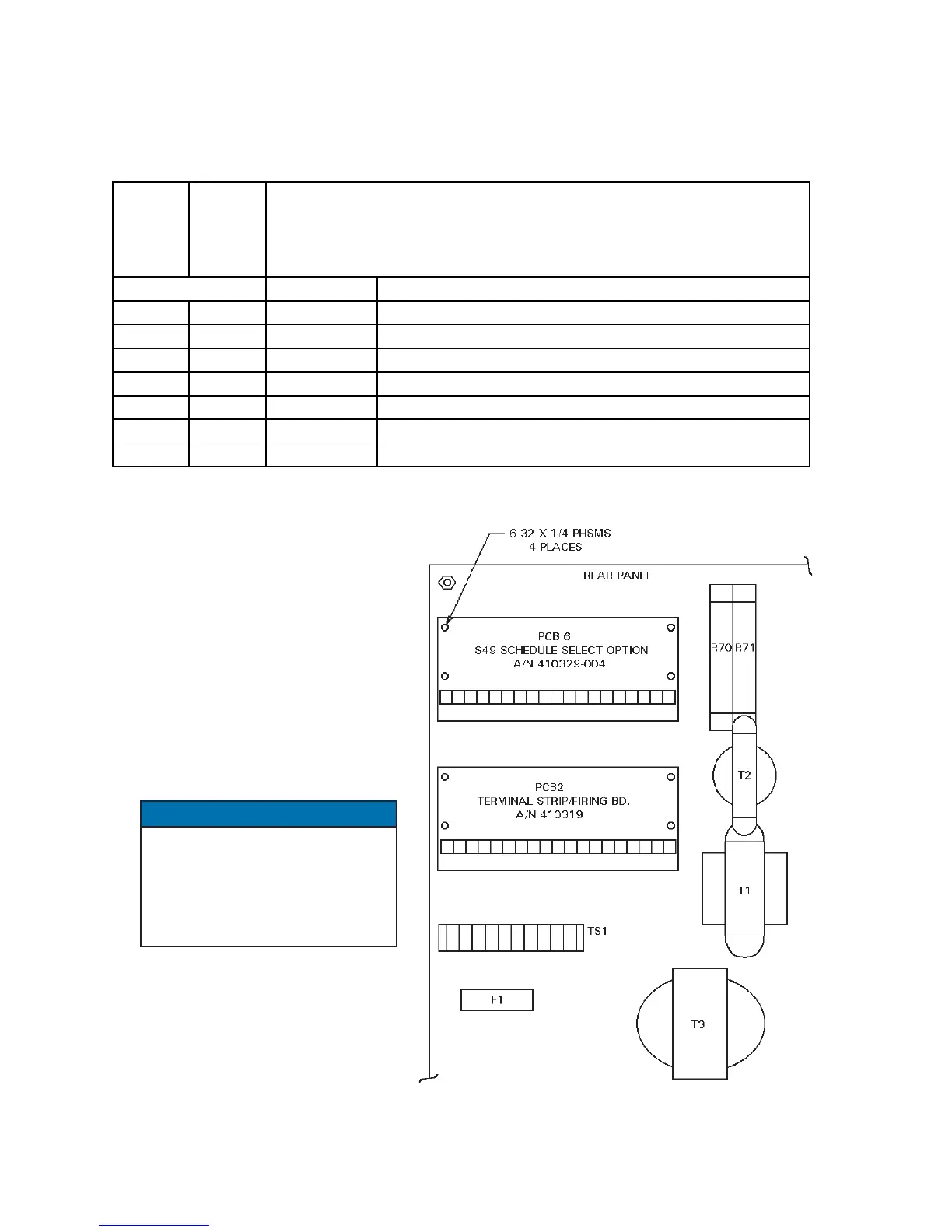
C-1.0 CUSTOMER INSTALLATION OF S49 SCHEDULE SELECT OPTION
In an existing EN1000 or EN1001 “T/D” or “L” Cabinet
1. Remove ALL power to control.
Open door.
2. Mount the S49 Option PCB (A/N
410329-004) to standoffs on rear
panel using four (4) 6-32 x 1/4
PHSMS, Phil., Brite (see Figure
C-1).
3. Connect J4-J4 Harness (A/N
322458) per Wiring Diagram
included with this kit.
On the Wiring Diagram, the dark
band on connectors indicates
stripe on ribbon harness. Harness
MUST be installed with ribbon
harness stripe oriented correctly.
4. Close door. Reapply power.
NOTICE
Figure C-1. Mounting detail for “T/D” or “L” Cabinet
600675-001
EN1000
600675
EN1001
PART NO. DESCRIPTION
1 600541-009 PCB Assem., Seq. Ctrl. Bd., EN1000/S49
1 600572-009 PCB Assem., Seq. Ctrl. Bd., EN1001/S49
1 421210-032 Wiring Diagram, EN1000/S49-Series, T/D/L Cabinet
1 421269-018 Wiring Diagram, EN1001/S49-Series, T/D/L Cabinet
1 1 410329-004 Assembly, PCB, S49 Option
1 1 322458 Harness Assembly, J4-J4
4 4 557003 6-32 x 1/4 PHSMS, Phil., Brite
QUANTITY
PARTS LIST

 Loading...
