ENTRON Controls, LLC. • 700120S • Page 147
C-2.0 CUSTOMER INSTALLATION OF S49 SCHEDULE SELECT OPTION
In an existing EN1000 or EN1001 “E” Cabinet
1. Remove ALL power to control. Open door.
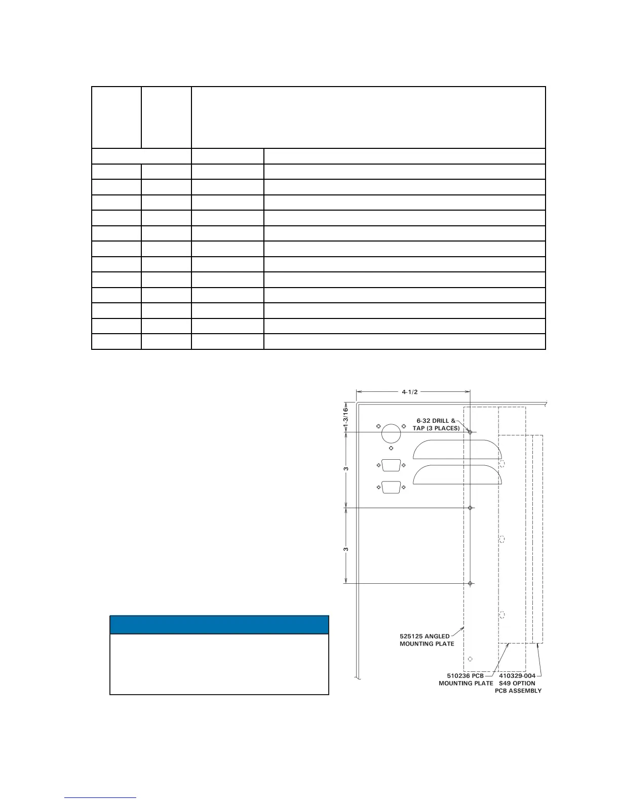
2. Drill rear panel of cabinet as indicated in
Figure C-2. Mount angled bracket (P/N
525125) using the 6-32 x 3/8 Screws, Split
Lockwashers and Nuts provided. Mount the
PCB Mounting Plate (A/N 510236) using three
(3) of the 6-32 x 1/4 Screws and Lockwashers.
3. Mount the S49 Option PCB (A/N 410329-004)
to standoffs on the PCB Mounting Plate with
the J4 connector at the top, using four (4) 6-32
x 1/4 PHSMS, Phil., Brite (see Figure C-2).
4. Connect J4-J4 Harness (A/N 322525) per
Wiring Diagram included with this kit.
On the Wiring Diagram, the dark band on
connectors indicates stripe on ribbon
harness. Harness MUST be installed with
ribbon harness stripe oriented correctly.
5. Vacuum or otherwise remove ALL metal chips.
Close door. Reapply power.
NOTICE
Figure C-2. Mounting detail for
“E” Cabinet
600675-003
EN1000
600675-002
EN1001
PART NO. DESCRIPTION
1 600541-009 PCB Assem., Seq. Ctrl. Bd., EN1000/S49
1 600572-009 PCB Assem., Seq. Ctrl. Bd., EN1001/S49
1 421212-009 Wiring Diagram, EN1000/S49-Series, E Cabinet
1 421268-012 Wiring Diagram, EN1001/S49-Series, E Cabinet
1 1 525125 Bracket, Terminal Strip/PCB Mtg.
1 1 510236 Assem., Mtg. Plate, Term Strip/Firing Bd.
1 1 410329-004 Assembly, PCB, S49 Option
1 1 322525 Harness Assembly, J4-J4
7 7 557003 6-32 x 1/4 PHSMS, Phil., Brite
3 3 557006 6-32 x 3/8 PHSMS, Phil., Brite
3 3 557017 #6 Split Lockwasher
3 3 557018 6-32 x 1/4 AF Hex Nut
QUANTITY
PARTS LIST

 Loading...
