Page 148 • 700120S • ENTRON Controls, LLC.
C-3.0 CUSTOMER INSTALLATION OF S49 SCHEDULE SELECT OPTION
In an existing EN1000 or EN1001 “S” Cabinet
1. Remove ALL power to control. Open door.
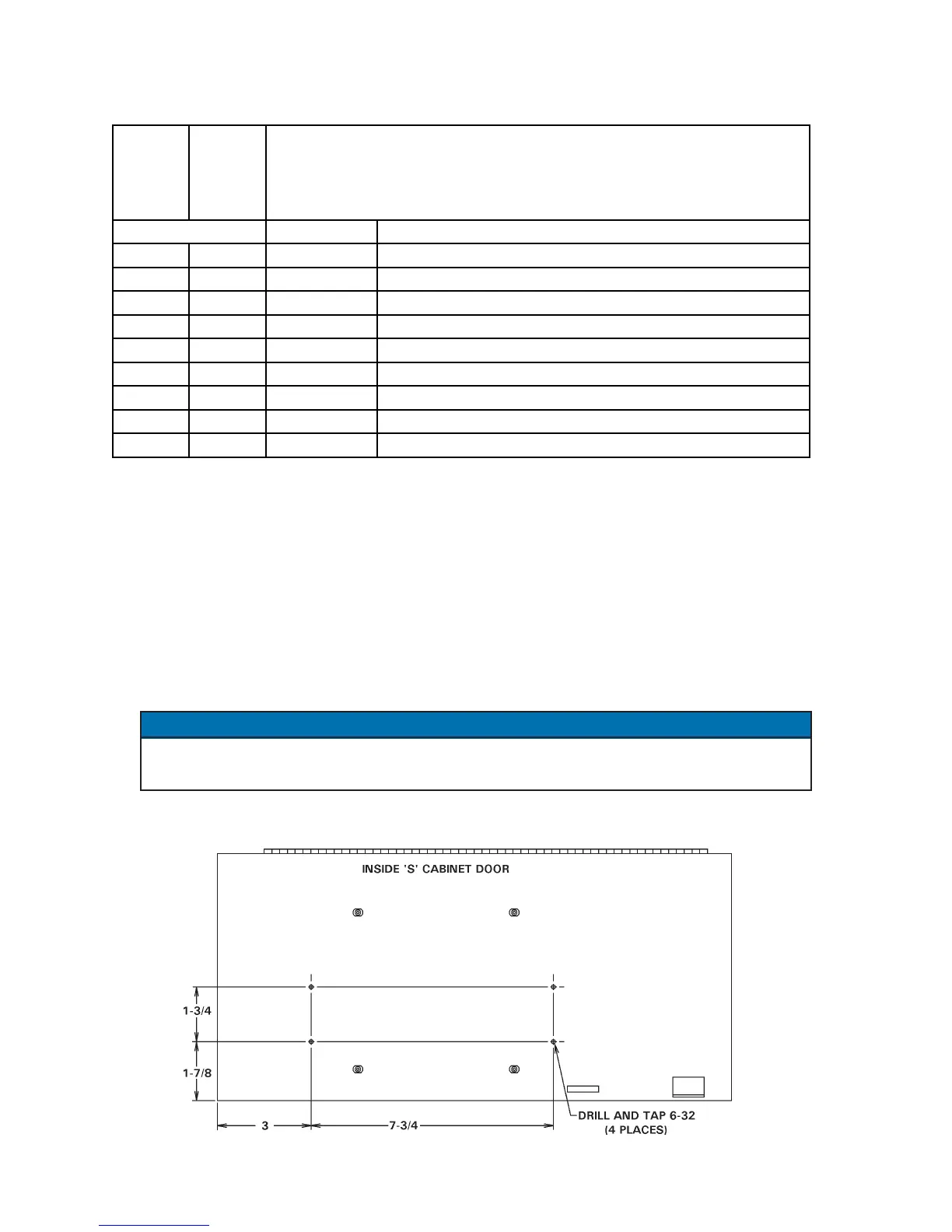
2. Drill and tap door of cabinet as indicated in Figure C-3. Install the standoffs by using four
(4) 6-32 x 3/8 Screws from the outside of the door, 6-32 x 1/2 standoffs on inside of the
door.
3. Mount the S49 Option PCB (A/N 410329-004) to the standoffs with the J4 connector towards
the rear panel of the cabinet, using four (4) 6-32 x 1/4 PHSMS, Phil, Brite.
4. Connect J4-J4 Harness (A/N 322539) per Wiring Diagram included with this kit.
On the Wiring Diagram, the dark band on connectors indicates stripe on ribbon harness.
Harness MUST be installed with ribbon harness stripe oriented correctly.
5. Vacuum or otherwise remove ALL metal chips. Close door. Reapply power.
NOTICE
Figure C-3. Mounting detail for “S” Cabinet
600675-005
EN1000
600675-004
EN1001
PART NO. DESCRIPTION
1 600541-009 PCB Assem., Seq. Ctrl. Bd., EN1000/S49
1 600572-009 PCB Assem., Seq. Ctrl. Bd., EN1001/S49
1 421180-010 Wiring Diagram, EN1000/S49-Series, S Cabinet
1 421270-008 Wiring Diagram, EN1001/S49-Series, S Cabinet
1 1 410329-004 Assembly, PCB, S49 Option
1 1 322539 Harness Assembly, J4-J4
4 4 557003 6-32 x 1/4 PHSMS, Phil., Brite
4 4 557006 6-32 x 3/8 PHSMS, Phil., Brite
4 4 555031 6-32 x 1/2 Standoff, Hex Threaded Brass
QUANTITY
PARTS LIST

 Loading...
