Page 16 • 700120S • ENTRON Controls, LLC.
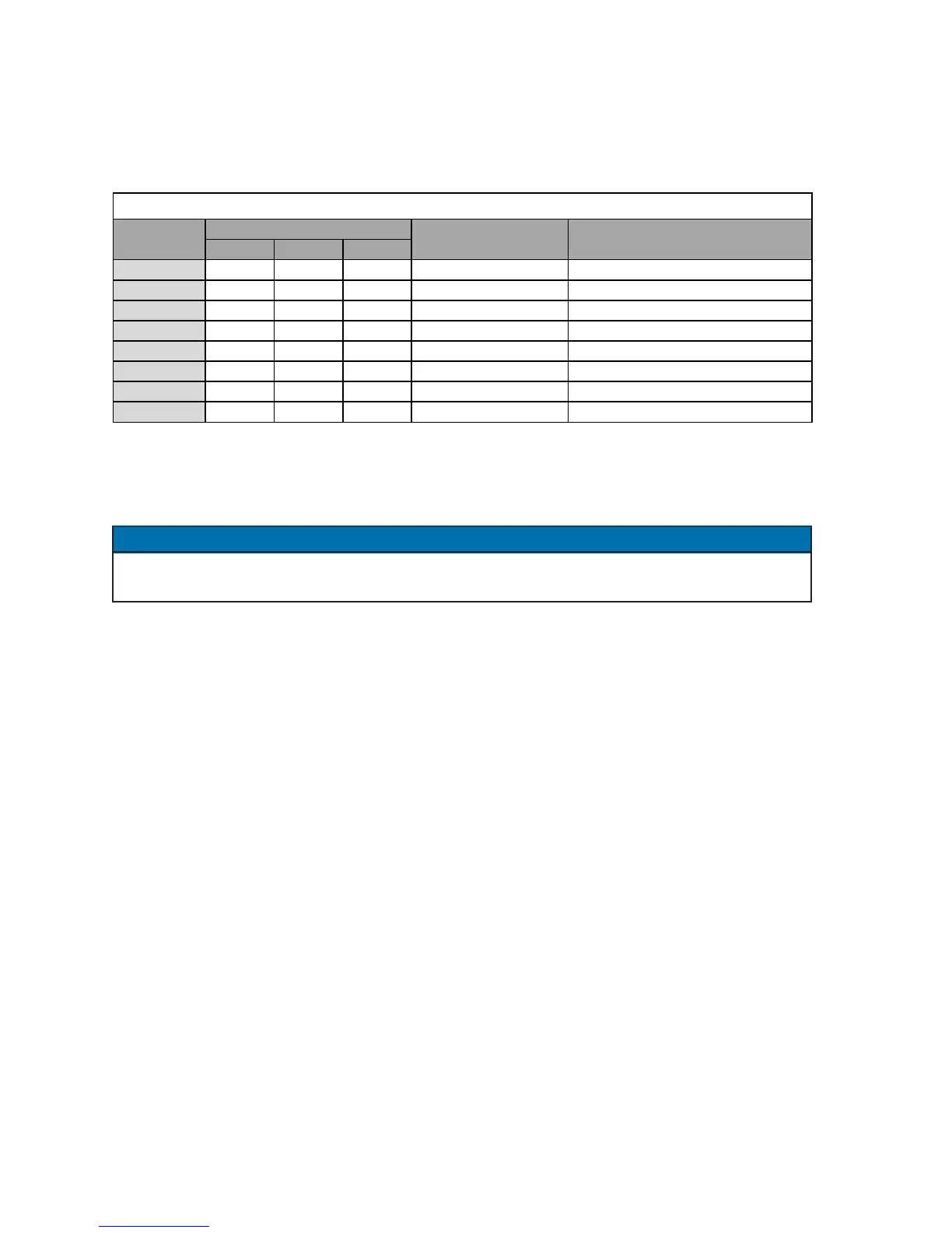
VALVE MODE (15) – The three solenoid valves are activated based on the code programmed
as shown in Table 2-3.
Table 2-3. VALVE codes
When in the PROGRAM mode and selection of a VALVE code is being made, the VALVE
indicator LEDs (29, 30, 31) will indicate the selected valve(s). The valve output will not be
energized while in PROGRAM mode.
The VALVE code indicated above can be programmed for different features such as PROCESS
OUTPUT (see Section 5.4.7).
2.3 OTHER PROGRAMMABLE SEQUENCE PARAMETERS (cont.)
NOTICE
VALVE3 VALVE2 VALVE1
00 OFF OFF OFF All valves off None
01 OFF OFF ON Valve 1 active SV1-SV2
02 OFF ON OFF Valve 2 active SV3-SV4
03 OFF ON ON Valves 1 & 2 active SV1-SV2 & SV3-SV4
04 ON OFF OFF Valve 3 active SV5-SV6
05 ON OFF ON Valves 1 & 3 active SV1-SV2 & SV5-SV6
06 ON ON OFF Valves 2 & 3 active SV3-SV4 & SV5-SV6
07 ON ON ON Valves 1, 2 & 3 active SV1-SV2, SV3-SV4 & SV5-SV6
VALVE Indicator LEDs
DescriptionVALVE code Valve Outputs on TS1
Since the VALVE codes are in binary form, valve assignments are clarified in this table.

 Loading...
