Page 38 • 700120S • ENTRON Controls, LLC.
4.6 NON-VOLATILE MEMORY ERROR
All ENTRON microprocessor based controls make extensive use of non-volatile memory devices
for parameter data storage. Although safety features (control relays and opto-isolation) are in
place to insure high voltage spikes do not appear on low voltage circuits, non-volatile memory
devices can sometimes be affected by improper hookup, electrical disturbances generated in
other equipment operating nearby, or in the welding machine itself.
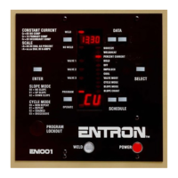
When an EN1000 or EN1001 Control is powered up or returns
from Emergency Stop condition, it executes a diagnostic test
that reads all memory locations within schedule storage areas.
If invalid data is stored in memory, control will display a flashing
3232
3232
32 in DATA display and
E.rE.r
E.rE.r
E.r
..
..
. in SCHEDULE display alternating
with schedule number where invalid data (error) is found. If
invalid data is found in EXTENDED FUNCTIONS’ memory
area,
E.rE.r
E.rE.r
E.r
..
..
. alternates with EXTENDED FUNCTION parameter
designation.
The ERROR
3232
3232
32 indication does not mean there has been damage
to welding control. It simply means something has caused invalid
data to be stored in one or more memory locations. The control
will not sequence until this error has been corrected.
To recover from this condition:
1. Press SELECT push button to stop flashing.
2. Place control in PROGRAM mode.
3. The operator can use SELECT to find function containing invalid data.
4. Use DATA push buttons to correct data.
5. Press ENTER.
6. Return control to OPERATE mode.
If more than one location has been affected, it may be necessary to use CLEAR ALL command
in EXTENDED FUNCTIONS to erase all memory locations and restore default settings (factory
settings).
Reoccurring ERROR
3232
3232
32 (ERROR
1414
1414
14 Flashing in previous revisions)
The effects of electrical disturbances can be minimized or prevented by observing the following
precautions when installing the welding control:
1. Make sure cabinet is properly grounded to power distribution system, nearby water
pipe or other effective building ground with a wire adequate for its application.
2. All wires connected to the pilot input terminals on the TS1 Terminal Strip (FS1, FS3,
FS7, FS11, PS1, ES1, NW1, TLS1, and their adjacent GND terminals) should be separated
as much as possible from other wires connecting to solenoid valves, welding transformers,
and the AC line. These pilot input wires should never be run through the same conduit
with solenoid, welding transformer and AC line wires. Connection of any GND terminal
to earth ground might cause ERROR
3232
3232
32 or even ERROR
1414
1414
14.
WRONG example for wiring and routing of low and high voltage wires in same conduit for
typical EN1000/EN1001 Series Controls is shown in Figure 4-10.
Figure 4-9.
Flashing
1414
1414
14 or
3232
3232
32 Errors

 Loading...