Page 78 • 700120S • ENTRON Controls, LLC.
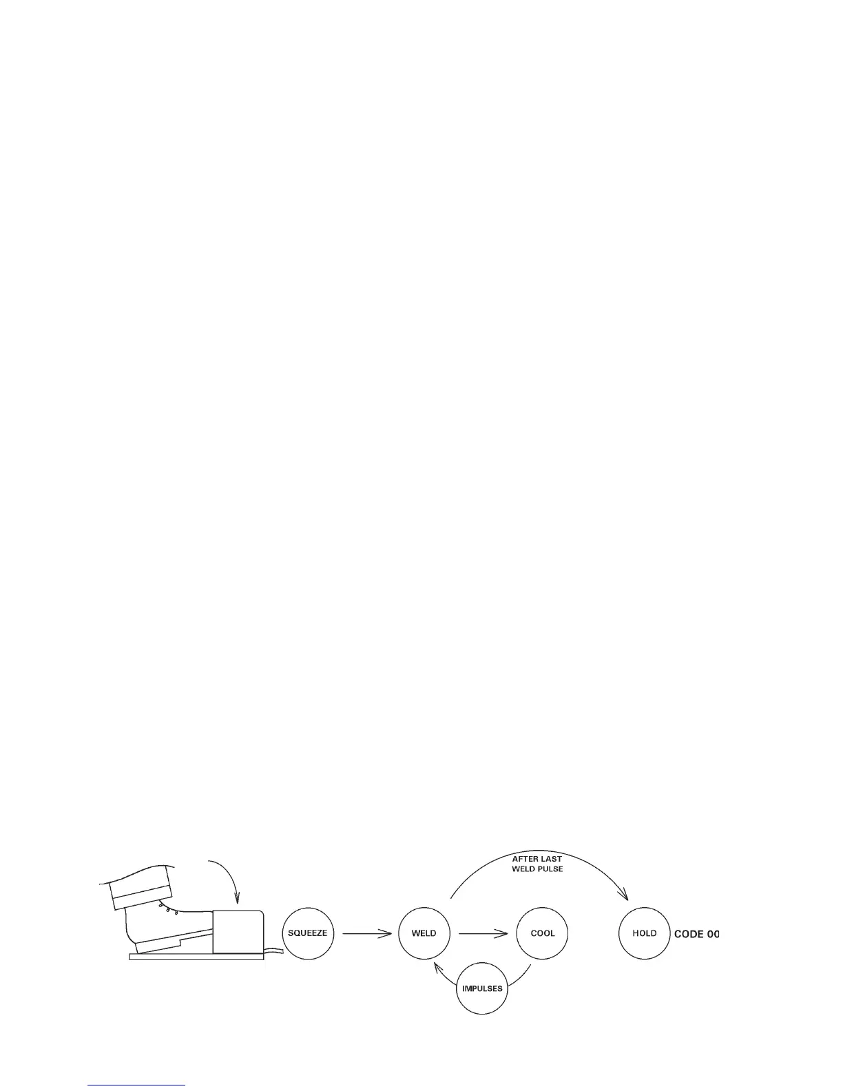
Figure 6-1. NON-REPEAT sequence
3. Program the schedule for the part to be welded. Place the work in the machine and set the
WELD/NO WELD switch (both on Control Panel and any External Weld/No Weld Switches)
to the WELD position. The machine is ready to weld.
4. If no standards have been set, it is recommended to use a short WELD count for initial setup
and welding. WELD count can be increased, the PERCENT CURRENT can be adjusted,
and welding transformer tap (if applicable) can be increased for the best weld. The most
efficient use of the control and welding machine will generally be made at the lowest welding
transformer tap, the highest PERCENT CURRENT setting, and the shortest WELD count.
5. For REPEAT operation, program CYCLE MODE to
0101
0101
01, and program OFF count to allow
sufficient time to reposition the part for subsequent welds.
6.2 CYCLE MODES
The EN1000/EN1001 can be programmed to operate in several CYCLE MODES. Each of the
50 possible schedules has a CYCLE MODE parameter that dictates the sequence of events that
will follow an initiation.
The CYCLE MODE are as follows:
0000
0000
00 = NON-REPEAT
0101
0101
01 = REPEAT
0202
0202
02 = CHAINED
0303
0303
03 = SUCCESSIVE
0404
0404
04 = CONDITIONAL SUCCESSIVE
0505
0505
05 = WAIT-HERE
The CYCLE MODE parameter is entered into a schedule when the control is in PROGRAM
mode with CYCLE MODE indicator LED illuminated.
6.2.1 NON-REPEAT – CYCLE MODE=
0000
0000
00
When any of the 50 possible schedules, having a CYCLE MODE setting of
0000
0000
00, is initiated by a
Pilot switch, the sequence executes as shown in Figure 6-1 (depending on the programmed
parameters).
Upon initiation, the programmed valve is energized at the beginning of SQUEEZE. If the Pressure
Switch is open, the control counts through the SQUEEZE time but does not begin counting
6.1 WELD SEQUENCE EXAMPLE (cont.)

 Loading...
