ENTRON Controls, LLC. • 700120S • Page 163
To install the IMU Control:
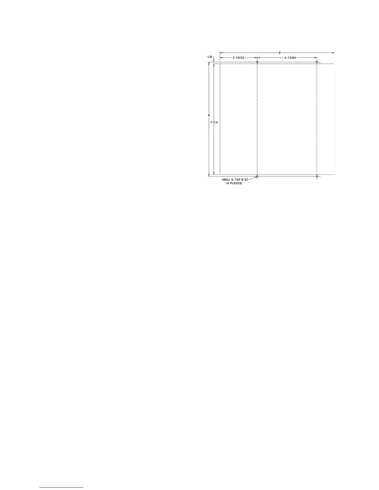
1. Modify enclosure to accept IMU per Figure
H-2.
2. Mount IMU Assembly to enclosure using four
(4) black 6-32 x 1/4 screws supplied in poly
bag taped to bottom of IMU.
3. Place supplied precautionary labels on interior
or exterior of enclosure as indicated:
a. “Danger, Hazardous Voltage from One
or More Sources...” Label (P/N 460142)
Should be placed on interior of
enclosure near points of exposed
hazardous voltage.
b. “Danger, Voltage and Flash Hazard”
Label (P/N 460143)
Should be placed near the fuse.
c. “Danger...Earth Ground” Label (P/N
460144)
Should be placed near customer connection to Earth Ground.
d. “Caution, Water Hose Burst Hazard” Label (P/N 460145)
Should be placed on exterior of enclosure for water-cooled contactors.
e. “Warning , Hazardous Voltage from One or More Sources...” Label (P/N 460146)
Should be placed on exterior of enclosure.
f. “Caution, Do Not Pinch Wires...” Label (P/N 460170)
Should be placed on interior of enclosure.
4. Complete hook-up of wiring to control per Wiring Diagram. See USED ON section below
for Wiring Diagram numbers.
Poly bag taped to bottom of IMU includes:
4 Ea. 6-32 x 1/4 PHSMS, Phil, Black................................... P/N 557004
4 Ea. 6-32 x 1/4 AF Hex Nut ................................................ P/N 557018
1 Ea. Label, “Danger, Hazardous Voltage...” ....................... P/N 460142
1 Ea. Label, “Danger, Voltage and Flash Hazard”................ P/N 460143
1 Ea. Label, “Danger...Earth Ground”.................................. P/N 460144
1 Ea. Label, “Caution, Water Hose Burst Hazard”............... P/N 460145
1 Ea. Label, “Warning , Hazardous Voltage...” .................... P/N 460146
1 Ea. Label, “Caution, Do Not Pinch Wires...” .................... P/N 460170
1 Ea, Resistor, Power, 2000 Ohm, 10W (For 575V) ............ P/N 600048
1 Ea, Jumper, TS1, 380 VAC Controls ................................. P/N 325225
When control is wired for either 230/460/575 VAC Operation, add quantity one (1) TS1
label P/N 460201 for 380 VAC Operation.
When control is wired for 380 VAC Operation, add quantity one (1) TS1 label P/N
460105 for 230/460/575 VAC Operation.
USED ON:
EN1001-IMU (SCR) Wiring Diagram 421423
EN1001-IMU/485 (SCR) Wiring Diagram 421423-002
EN1001/VS-IMU (SCR) Wiring Diagram 421423-003
EN1000-IMU (SCR) Wiring Diagram 421424
Modification to
customer supplied
enclosure for IMU
mounting.
(Not to scale)
APPENDIX H IMU MOUNTING OPTIONS (cont.)
Figure H-2. IMU enclosure modification

 Loading...
