ENTRON Controls, LLC. • 700120S • Page 159
APPENDIX F EN1003 THREE PHASE DC CONTROLS (cont.)
Correct phase rotation is indicated by the red LED (L1 in Figure F-2) on PCB3 as described in
Note 2 on Wiring Diagrams. Incorrect phase rotation or a missing phase will result in LED not
being lit.
The control may be operated on 60 Hz or 50 Hz. On PCB3, set SW1 position #3 (Figure F-2) to
ON for 60 Hz, OFF for 50 Hz. Also see Note 2 on Wiring Diagrams.
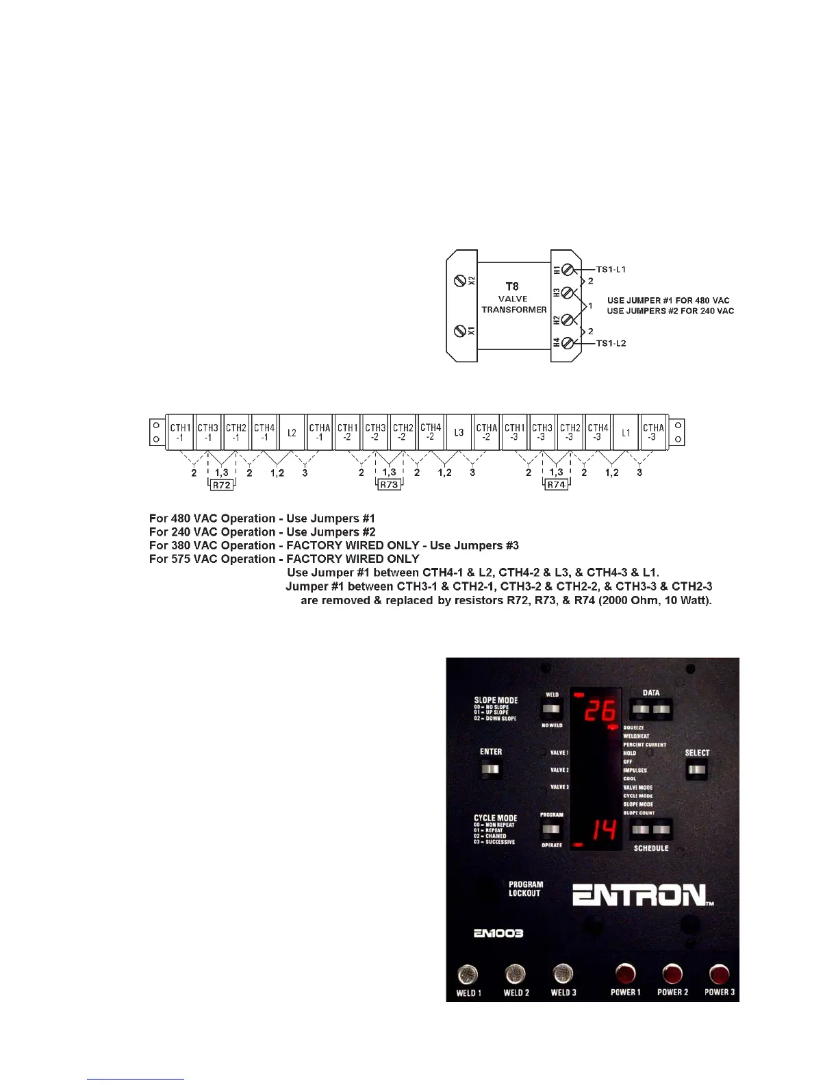
Nominal line voltages of 240 and 480 may be
used and selected by jumpers on T8
Transformer (Figure F-3) and TS1 Terminal
Strip (Figure F-4) as described in Note 2 on
Wiring Diagrams. 380 and 575 volts may also
be used, but both require special factory wiring.
If line voltage, frequency, and inside delta,
outside delta, or “Y” are specified when
ordering the control, it will be set up at the
factory as described above.
Six lights on the Front Panel (Figure F-5)
indicate power in each phase and voltage across
each welding transformer primary.
Three fuses (F1, F2 and F3 – 1/4A) protect the
control circuits in each phase. Fuses F6, F7,
and F8 (2AG 1A) protect the valve circuits for
each of the solenoid valve outputs.
Figure F-3. T8 jumper settings
Figure F-4. TS1 jumper settings
Figure F-5. EN1003 Front Panel

 Loading...
