EPSON Stylus Pro 9000
Disassembly & Assembly 89
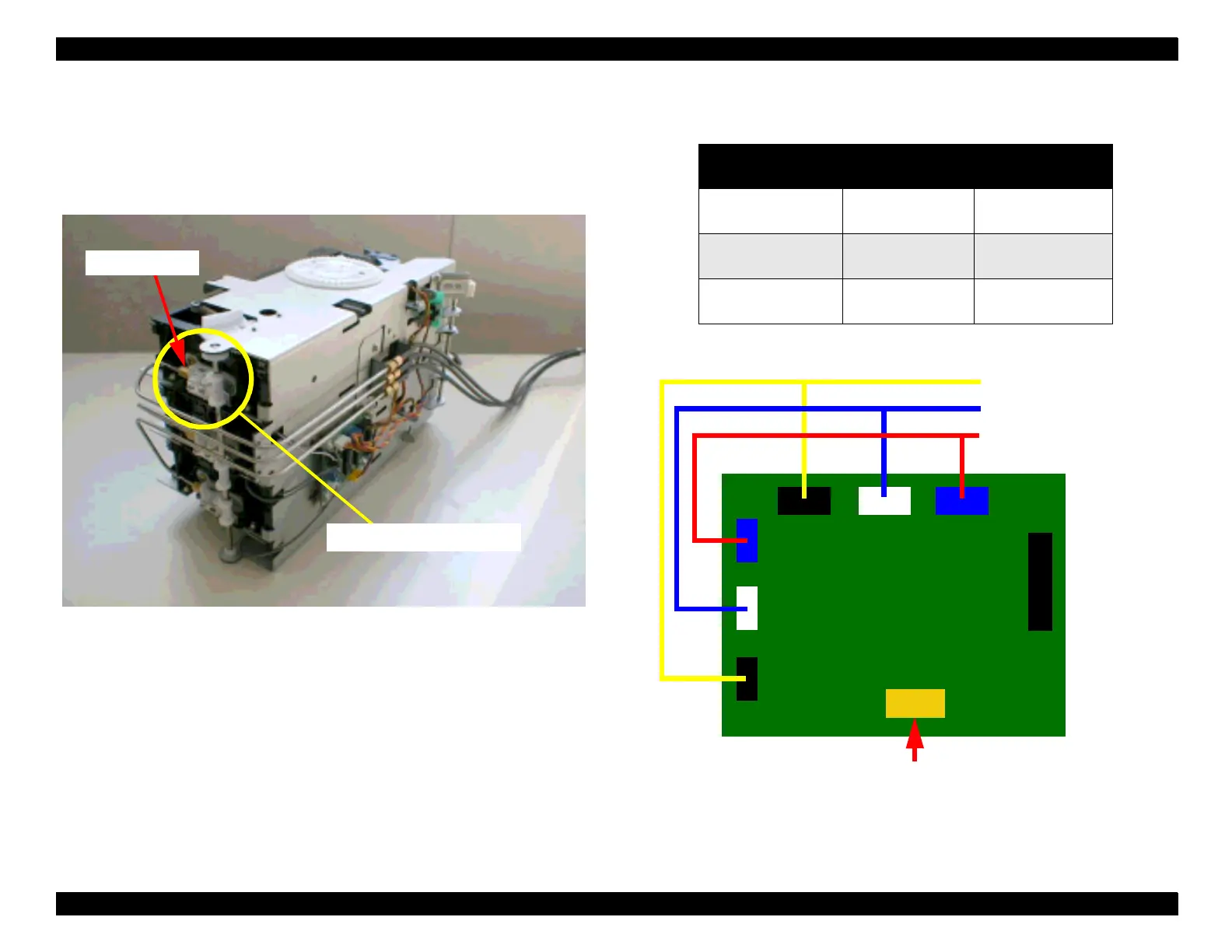
14. Loosen the lock nut and remove the ink pipe from “HOLDER ASSY.,
VALVE, A” of the I/C holder.
15. Remove the two cables corresponding to the I/C holder to be removed
from the connector on the I/H relay board.
Figure 4-58. Removing the ink pipe
Figure 4-59. Connector location on the I/H relay board
Lock Nut
HOLDER ASSY., VALVE,A
Table 4-3. Connection between each I/C holder and relay board
I/C Holder I/C ID sensor
I/C sensor
and Ink low sensor
Black
(Light Cyan)
CN3 CN4
Cyan
(Light Magenta)
CN5 CN6
Magenta
(Yellow)
CN7 CN8
CN3
CN5
CN7
CN4
CN6
CN8
CN1
Black / LC Holder
Cyan / LM Holder
FFC
I/H position sensor
Magenta / Yellow Holder
CN2

 Loading...


