EPSON Stylus Pro 9000
Disassembly & Assembly 88
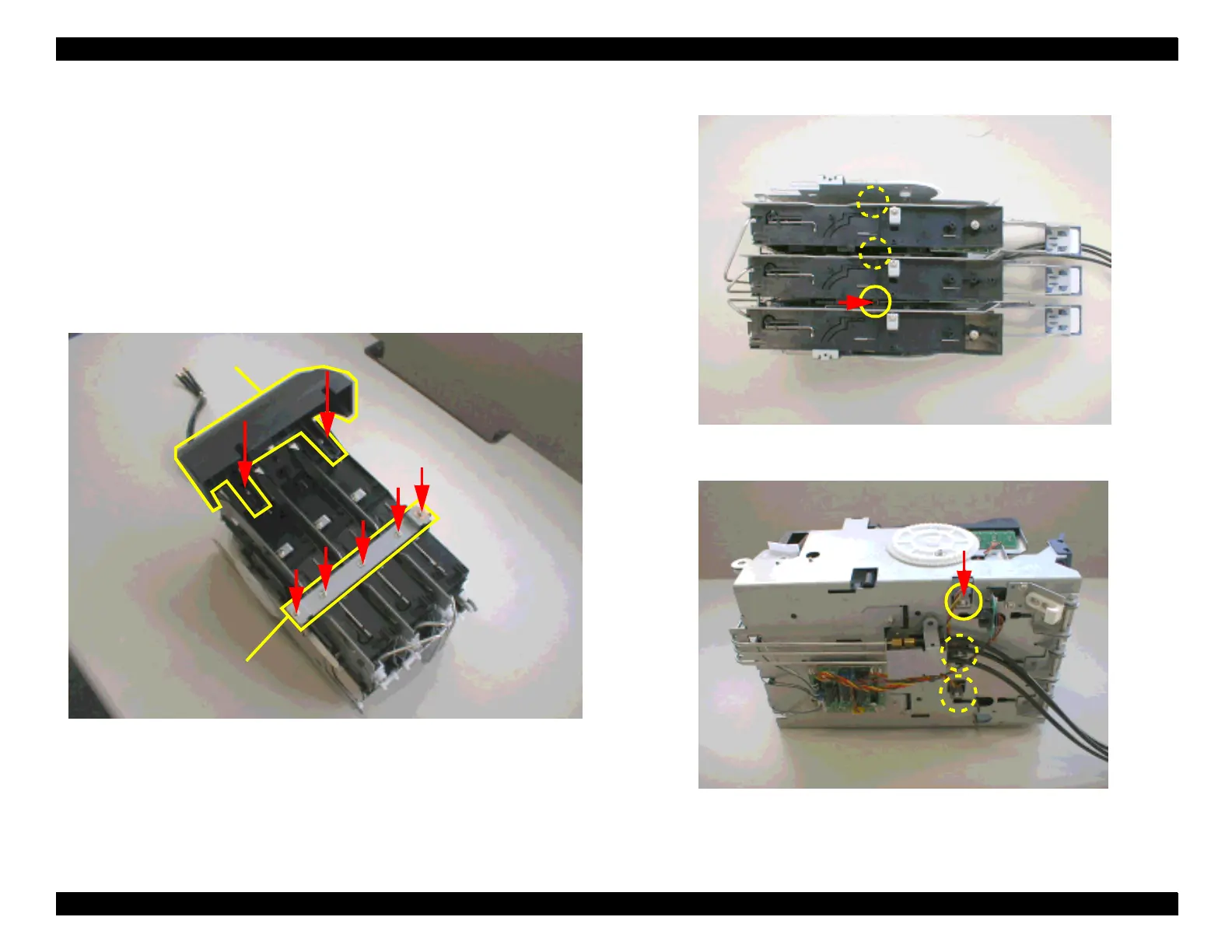
10. Remove the I/C holder assembly from the I/H assembly frame.
11. Remove the two screws (CP(W2) M3x4) securing the I/C cover to the I/C
holder assembly. Then, remove the five screws (2 pcs=CP(W2) M3x4,
3 pcs=P-Tight M3x4) securing the I/C holder fixing plate.
12. The I/C holder for each color can be removed individually. To remove one
of the I/C holder assembly, remove the one screw (CP(W2) M3x12)
securing the I/C holder assembly to a base frame of the I/H assembly.
13. Turn the I/C holder assembly upside down and remove the one screw
(CP(W2) M3x4) securing the I/C holder from the back of the base frame.
Figure 4-55. Removing the I/C cover and the fixing plate
Figure 4-56. Removing the screw (from the top)
Figure 4-57. Removing the screw (from the bottom)
I/C Cover
I/C Holder Fixing Plate

 Loading...


