EasyManuals Logo

Epson Stylus Pro 9000 - Print Engine User Manual

Epson Stylus Pro 9000 - Print Engine
198 pages
To Next Page IconTo Next Page
To Previous Page IconTo Previous Page
Page #87 background imageLoading...
Page #87 background image
EPSON Stylus Pro 9000
Disassembly & Assembly 87
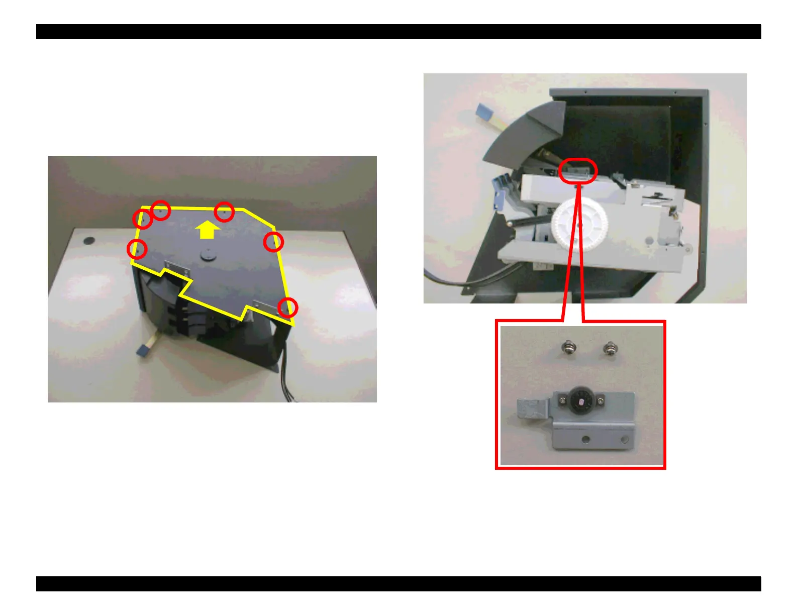
8. Remove the six screws (CP(W2) M2x4) securing the side cover of the I/H
assembly and remove the side cover.
9. Slightly rotate the I/C holder assembly so that the assembly is released
from the lock lever unit. Then remove the two screws (CP(W2) M3x6)
securing the friction gear assembly and remove the assembly.
Figure 4-53. Removing the side cover of I/H assembly
Figure 4-54. Removing the friction gear assembly.
Remove

Table of Contents

Questions and Answers:

Question and Answer IconNeed help?

Do you have a question about the Epson Stylus Pro 9000 - Print Engine and is the answer not in the manual?

Epson Stylus Pro 9000 - Print Engine Specifications

General IconGeneral
BrandEpson
ModelStylus Pro 9000 - Print Engine
CategoryPrinter
LanguageEnglish

Related product manuals