EasyManua.ls Logo

Esser 8000C - Page 140

Esser 8000C
190 pages
Print Icon
To Next Page IconTo Next Page
To Previous Page IconTo Previous Page
Loading...
Page 140
Fire Alarm Computer 8000C / M
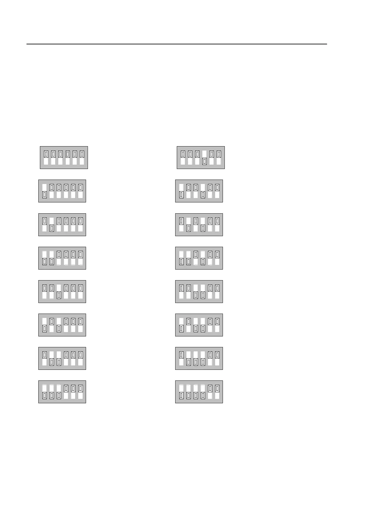
Example showing how to set the control panel address
The relevant address (control panel number) for each fire alarm control panel in the essernet
®
system is set on the essernet
®
module. The addresses must be set consecutively from address 1
to address 31 for all essernet
®
devices in the essernet
®
system.
The address (control panel number) set here on the essernet
®
module must also be programmed
with the service PC (menu item: System/control panels) in the customer data for the fire alarm
control panel.
Do not change factory-set position (ON) of DIP-switch no. 6 !
This switch is intended for in-factory testing purposes.
e
ssernet
module
1
2
3
4
5
6
1
2
4
8
16
1
2
3
4
5
6
1
2
4
8
16
1
2
3
4
5
6
1
2
4
8
16
1
2
3
4
5
6
1
2
4
8
16
1
2
3
4
5
6
1
2
4
8
16
1
2
3
4
5
6
1
2
4
8
16
1
2
3
4
5
6
1
2
4
8
16
1
2
3
4
5
6
1
2
4
8
16
Control panel adress 1
Control panel adress
2
Control panel adress
3
Control panel adress
4
Control panel adress
5
Control panel adress
6
Control panel adress
7
Control panel adress
8
ON
ON
ON
ON
ON
ON
ON
ON
1
2
3
4
5
6
1
2
4
8
16
1
2
3
4
5
6
1
2
4
8
16
1
2
3
4
5
6
1
2
4
8
16
1
2
3
4
5
6
1
2
4
8
16
1
2
3
4
5
6
1
2
4
8
16
1
2
3
4
5
6
1
2
4
8
16
1
2
3
4
5
6
1
2
4
8
16
1
2
3
4
5
6
1
2
4
8
16
Control panel adress
9
Control panel adress
10
Control panel adress
11
Control panel adress
12
Control panel adress
13
Control panel adress
14
Control panel adress
15
Control panel adress
16
ON
ON
ON
ON
ON
ON
ON
ON

Table of Contents

Related product manuals