Page 178
Fire Alarm Computer 8000C / M
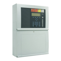
Example of essernet
®
diagnostic line with four fire alarm control panels
Fig. 24: Exaple essernet
®
diagnostic line with four control panel
In the illustrated example, four fire alarm control panels are interconnected in the essernet
®
.
The connection between control panel No. 2 and No. 3 is faulty due to an open line, a short circuit
or incorrect wiring.
Panel no. 5-31 are displayed with the ?-sign, because the they are not programmed in the
customer data.
☞
During the display of the essernet
®
diagnostic line, status messages such as
MB switched
off
or
Acoustics switched off
are not shown in this line of the display.
ommissioning / Servicing
control panel no. 5-31 non existant
 Loading...