Fire Alarm Computer 8000C / M
Page 71
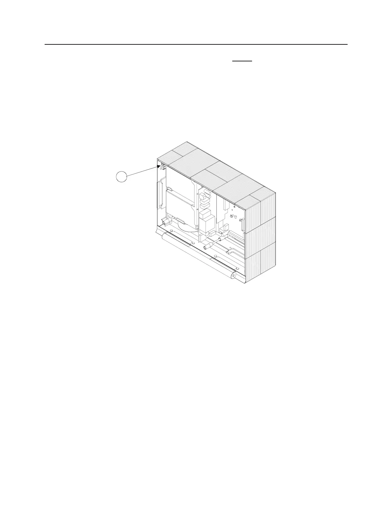
4. Insert the cover contact into the holder on the right or left upper
housing side. The contact lug
must be directed downwards (see Figure). The cover contact is already connected at the
factory to the basic module’s plug contact via a connecting cable.
The cover contact can be removed from the holder again for servicing and maintenance work
or, if necessary, additional cover contacts can be inserted into the remaining holders in each
corner of the housing. A total of four cover contacts can be inserted into the housing of the
FACP 8000C. When a single cover contact is installed, it should always be inserted into one of
the two holders in the upper part of the housing.
Fig. 17: Fitted housing without operating module / housing door (example 8000C)
A
Cover contact
5. Place the operating module with both retaining bolts into the housing frame. When doing so,
press the retaining bolts into the guide sleeve as far as they will go.
6. This completes assembly of the central housing.
Assemb