3025EMC Master Control Switching & Channel Branding
Revision 3.0.3 Page 11
Power should be applied by connecting a three-wire, grounding-type power supply cord to the power
entry module on the rear panel of each power supply. For use in North America, the power cord
should be a minimum 18 AWG wire size; type SVT marked VW-1, maximum 2.5 m in length. For use
outside North America, use a power cord approved for the country of use with a minimum 1.00 mm
2
wire size.
CAUTION: To reduce the risk of electric shock, grounding of the ground pin
of the main plug must be maintained.
2.6.2. Turning the Power On and Off
Each power supply is fitted with its own power switch. When the switch is turned off, the remaining
power supply will power the frame. To completely remove power from the frame, both power supplies
must be turned off.
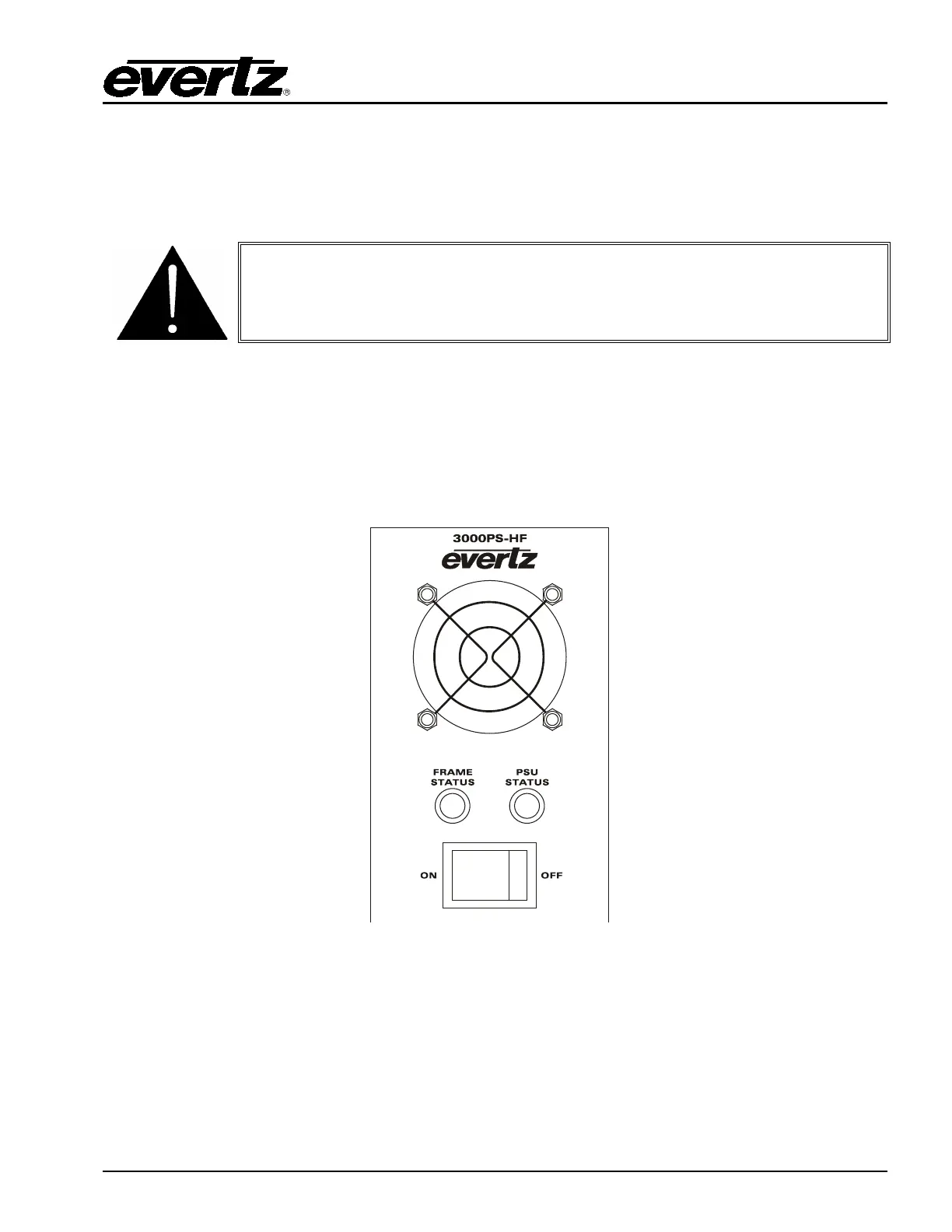
2.6.3. Power Supply Status Indicators
Figure 2-3: Power Supply Status Indicators
Each power supply has two status indicator LEDs. The green PSU STATUS LED indicates the health of
the local power supply. The red FRAME STATUS LED indicates the health of the entire frame and is
operated by the frame status buss of the frame. The FRAME STATUS LED will be OFF under normal
conditions and ON when there are Frame Status Fault conditions. See section 2.7 for more information
about the frame status buss fault conditions.