3025EMC Master Control Switching & Channel Branding
Page 20 Revision 3.0.3
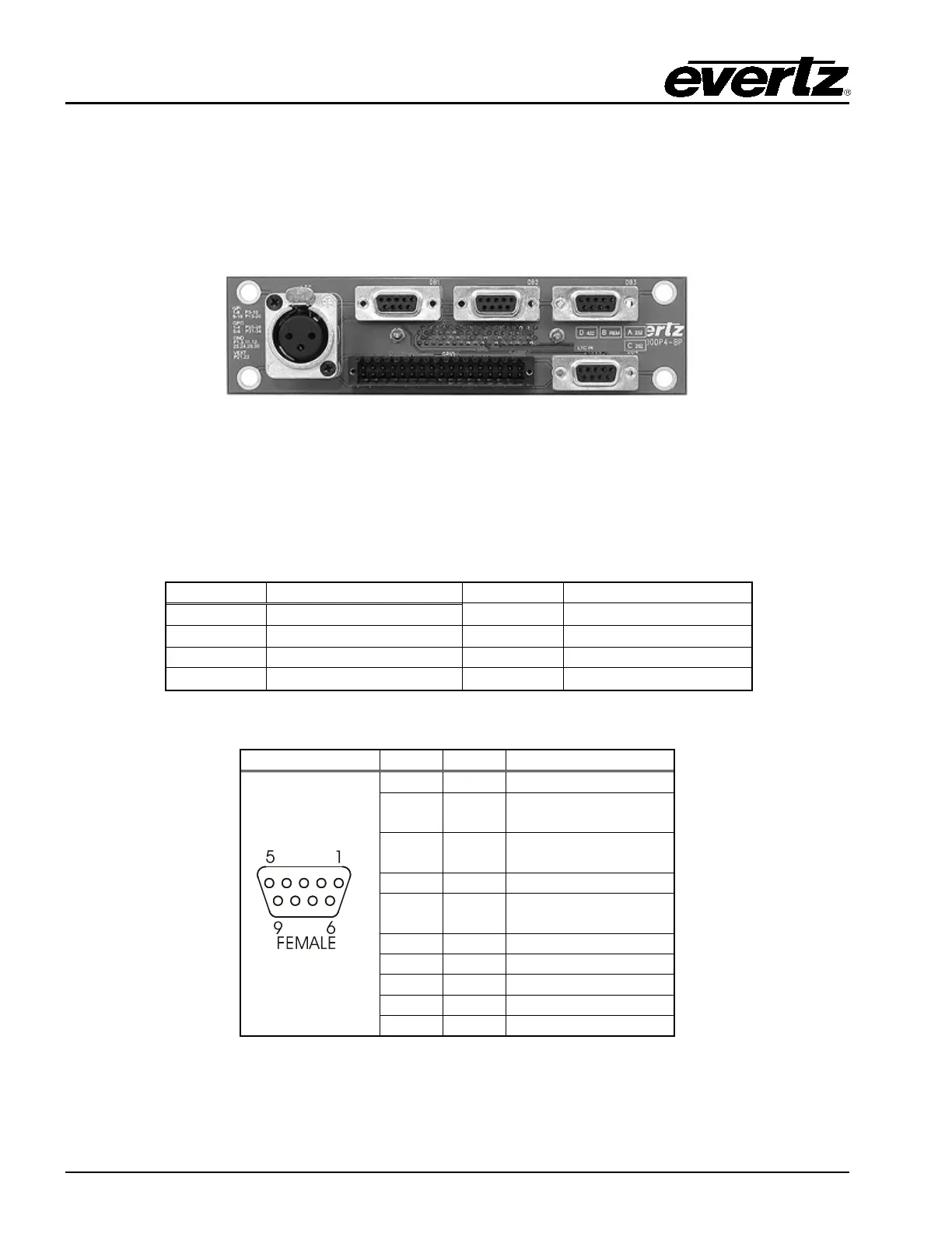
2.9.5. AUX IO-1 and AUX IO-2
There is one breakout panel provided with each EMC module. In order to access additional serial I/O
connections, connect the breakout panel (using the provided cable) to the AUXIO-1 connector. This will
allow the user to access LTC IN, GPIO, DB1, DB2, DB3, and DB4. See section 2.9.5.1 for a description
of the different ports. A secondary breakout panel can be added (optional) to AUXIO-2 connector; this
provides the user access to GPIO, DB5 and DB6.
Figure 2-8: Breakout Panel
2.9.5.1. Serial I/O on the Breakout Panel
The AUXIO-1 panel has four serial ports that can be used. The functions can be configured using EMC-
Setup. The ports are divided into two ports that are RS-232 and two that are RS-422. Before the serial
ports can be used they must be configured from the EMC-Setup program to have the controlling protocol
and baud rates set correctly. AUXIO-2 has two additional serial ports that can be used.
Table 2-1: Serial Ports
2
TxD
3
RxD
5
Table 2-2: RS-232 Pin Outs