3025EMC Master Control Switching & Channel Branding
Page 24 Revision 3.0.3
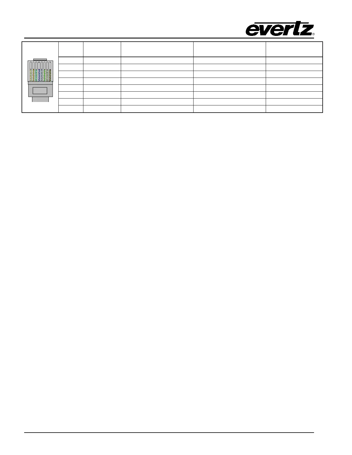
Pin 1
Pin # Signal EIA/TIA 568A
AT&T 258A or
EIA/TIA 568B
Table 2-7: Standard RJ45 Wiring Colour Codes
Note the following cabling information for this wiring guide:
• Only two pairs of wires are used in the 8-pin RJ 45 connector to carry Ethernet signals.
• Even though pins 4, 5, 7 and 8 are not used, it is mandatory that they be present in the cable.
• 10BaseT and 100BaseT use the same pins; a crossover cable made for one will also work with
the other.
• Pairs may be solid colours and not have a stripe.
• Category 5 cable must use Category 5 rated connectors.
The maximum cable run between the 3025EMC and the supporting hub is 300 ft (90 m). The maximum
combined cable run between any two end points (i.e. 3025EMC and PC/laptop via network hub) is 675
feet (205 m).
Devices on the Ethernet network continually monitor the receive data path for activity as a means of
checking that the link is working correctly. When the network is idle, the devices also send a link test
signal to one another to verify link integrity. The rear panel is fitted with two LEDs to monitor the Ethernet
connection.
10/100: This LED is ON when a 100Base-TX link is last detected. The LED is OFF when a 10Base-
T link is last detected. Upon power-up the LED is OFF as the last detected rate is not
known and therefore defaults to the 10Base-T state until rate detection is completed.
LN/ACT: This dual purpose Green LED indicates that the EMC has established a valid link to its
hub, and it determines whether the EMC is sending or receiving data. This LED will be
ON when the EMC has established a good link to its supporting hub. This gives you a
good indication that the segment is wired correctly. The LED will BLINK when the EMC is
sending or receiving data. The LED will be OFF if there is no valid connection.
2.12. CONTROL PANEL INSTALLATION: QMC-CP-1000E, QMC-CP-E & QMC-CP2048E
The QMC-CP-1000E, QMC-CP-E and QMC-CP2048E are fully programmable panels and therefore
the operation of the panel is entirely dependent upon its configuration. The QMC-CP-1000E has 16
physical buttons. The QMC-CP-1000E panel is ideal in applications emergency Program bus panel is
required.
The QMC-CP-E is a 2RU control panel that has 33 physical buttons. The QMC-CP-E panel can be
used for applications where a compact control panel is required.
The QMC-CP-2048E is a 2RU control panel that has 48 physical buttons. The QMC-CP-2048E panel
can be used for applications where multicast control or buddy panel operation is required.