3025EMC Master Control Switching & Channel Branding
Revision 3.0.3 Page 23
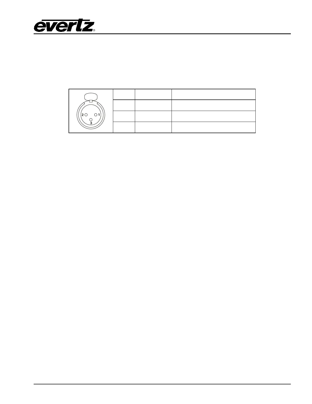
2.9.5.4. Linear Timecode
LTC IN: This female XLR connector on the breakout panel is an input for SMPTE/EBU linear
time code for driving the internal clock for the insertion of “Breakfast” clock style logos.
When using an unbalanced input source, the signal should be applied to pin 3 of the
LTC IN connector. Normally, the unused input (pin 2) should be connected to ground
(pin 1).
Pin # Name Description
1 GND Signal Ground.
2 LTC IN+ LTC In + input
3 LTC IN- LTC in – input
Table 2-6: LTC IN Pin Definitions
2.10. CONNECTING THE LINEAR TIME CODE
The EMC has a linear time code (LTC) input used to provide time information for the analogue or digital
clock logos. Connect the LTC output from your house master time code source to the LTC IN XLR
connector on the breakout panel. When using an unbalanced input to the reader, the signal should be
applied to pin 3 of the LTC input connector. Normally, the unused input (pin 2) should be connected to
ground (pin 1).
2.11. ETHERNET CONNECTIONS
ETH A: This RJ-45 connector is an Ethernet port used for EMC configuration downloads, control
panels, high-speed firmware upgrades, logging, SNMP and FTP Media/DVE Move
transfers.
ETH B: This RJ-45 connector is an Ethernet port used for EMC configuration downloads, control
panels, high-speed firmware upgrades, logging, SNMP and FTP Media/DVE Move
transfers.
2.11.1.1. Connecting to an Ethernet Network
The EMC is designed to be used with 10Base-T (10 Mbps), 100Base-TX (100 Mbps) or Gigabit (1Gbps)
twisted pair Ethernet cabling systems. When connecting for 10Base-T systems, category 3, 4, or 5 UTP
cable as well as EIA/TIA – 568 100Ω STP cable may be used. When connecting for 100Base-TX
systems, category 5 UTP cable is required. The cable must be “straight-through” with a RJ-45 connector
at each end. Establish the network connection by plugging one end of the cable into the RJ-45
receptacle of the EMC Series Keyer and the other end into a port of the supporting hub.
The straight-through RJ-45 cable can be purchased or can be constructed using the pinout information
in Table 2-7. A colour coded wiring table is provided in Table 2-7 for the current RJ 45 standards
(AT&T 258A or EIA/TIA 258B colour coding shown). Also refer to the notes following the table for
additional wiring guide information.