3025EMC Master Control Switching & Channel Branding
Revision 3.0.3 Page 21
2
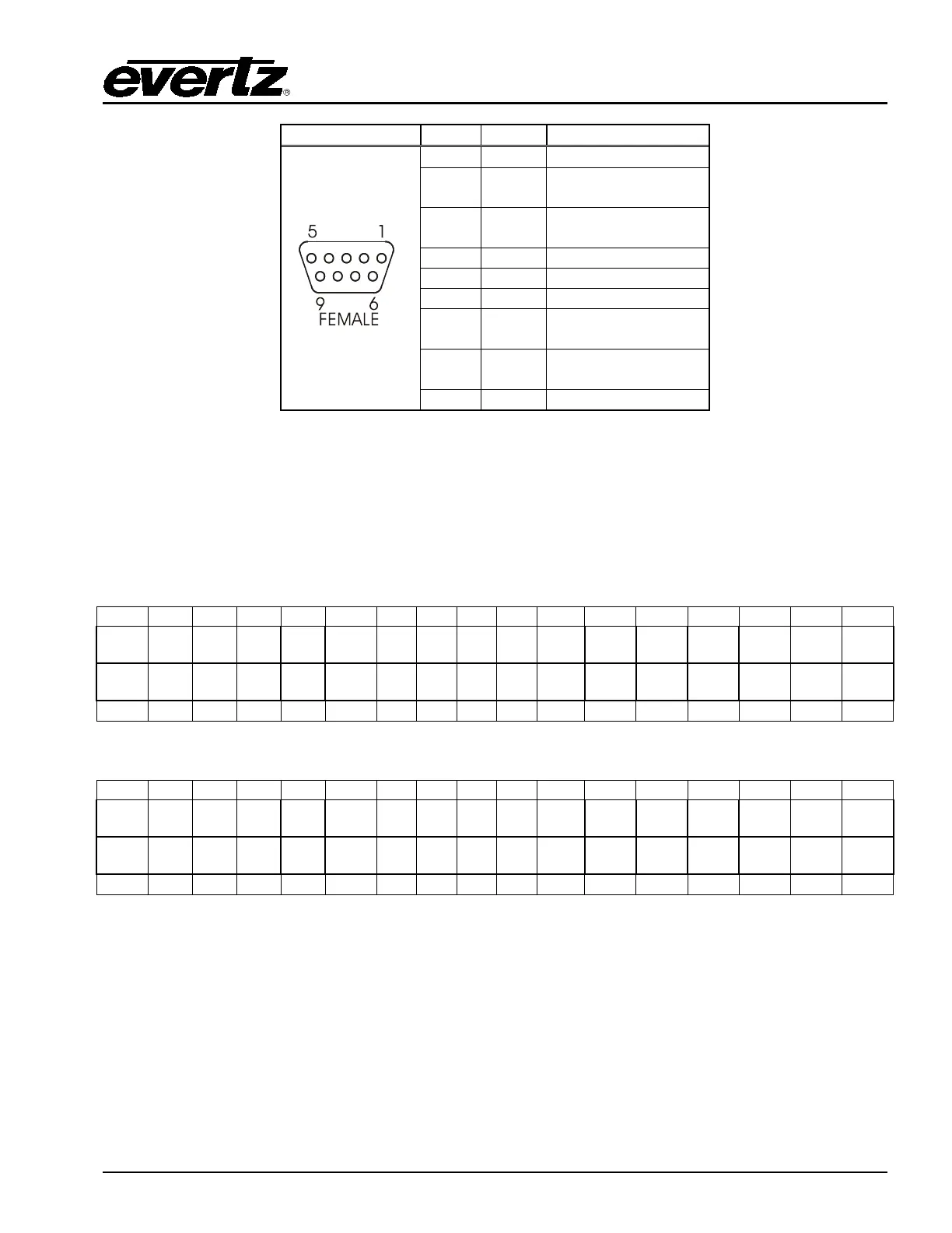
Tx-
3
Rx+
7
Tx+
8
Rx-
Table 2-3: RS-422 Pin Outs
2.9.5.2. GPI/O Connections
GPI/O: The Breakout panel contains the 34 pin terminal block that allows 8 general-purpose
control inputs and 8 general-purpose outputs. The AUXIO-1 panel provides GPIs 1-8 and
GPOs 1-8 and AUXIO-2 panel provides GPIs 9-16 and GPOs 9-16. In each case the GPI
and GPO number matches the EMC-Setup configuration.
Table 2-4: AUX IO 1 GPI/O Logical Connector
Table 2-5: AUX IO 2 GPI/O Logical Connector (optional)
2.9.5.3. CONNECTING THE GENERAL PURPOSE INPUTS AND OUTPUTS
GPI interfacing with the EMC is possible through general-purpose inputs and outputs available on the
9700BHP-AUX breakout panels. The GPIs are active low with internal pull-up resistors (4.7k Ohms) to
+5 V. To make an input active, lower the signal to near ground potential (i.e. connect to shell or
chassis ground). This can be done with a switch, relay, TTL drive, GPO output, or using another similar
method. Figure 2-9 shows the input circuit for the general-purpose inputs.