Falcon M-Class | User Guide
43
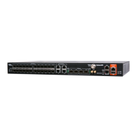
4.5.3 SFP Operational Range
This section shows SFP operational range
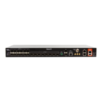
If you insert SFPs into port s 7 and 8 you get the following display which show
the operational range. The red indicators under status imply a low Rx error since
there is no reception
Figure 4-16: Operational Range
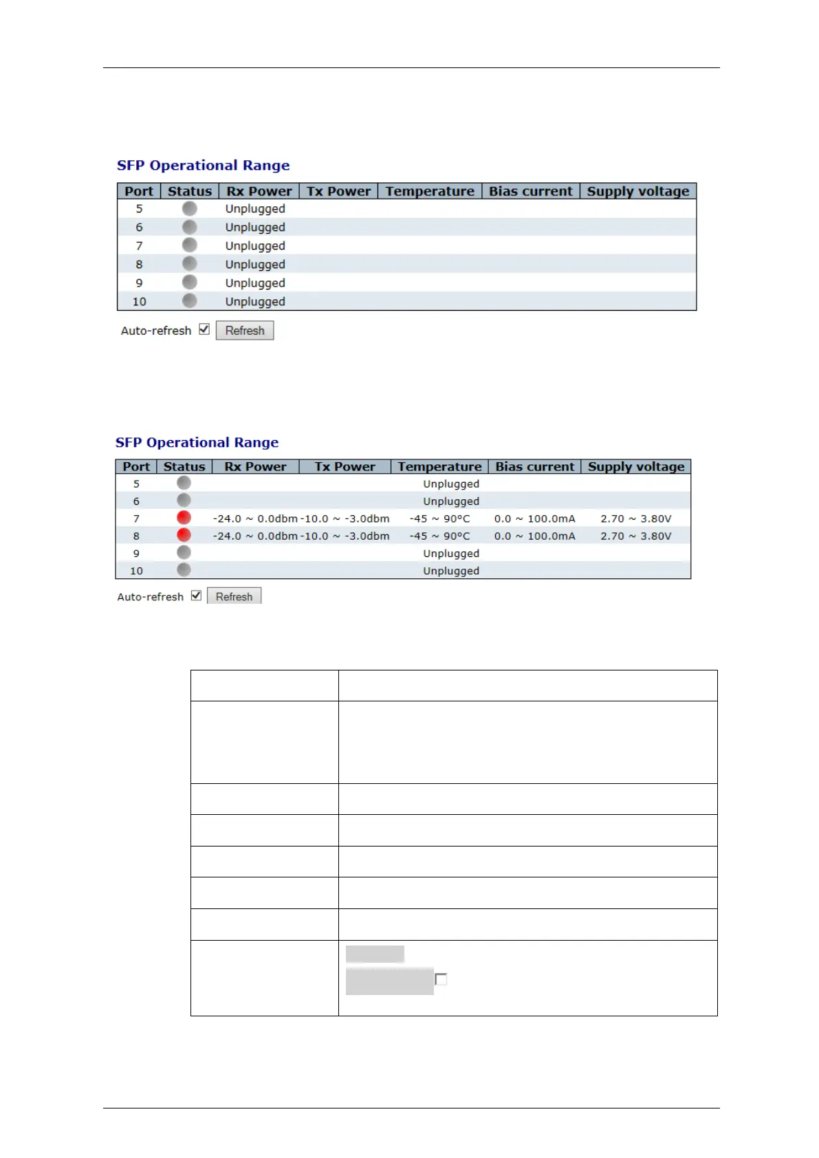
Table 4-14: SFP Operational Range Parameters
The physical port in which the SFP is installed
The status of the SFP port: grey=unplugged
Red=when SFP is plugged and operational; Green when
the SFP is connected to another similar SFP (installed in
another device)
Module's allowed receive optical power range [dBm].
Module's allowed transmit optical power range [dBm]
Module's allowed internal temperature range.
Module's allowed transmitter bias current range [mA].
Module's allowed supply voltage range [V].
Refresh: Click to refresh the page immediately
Auto-refresh : Check this box to enable an automatic
refresh of the page at regular intervals
 Loading...