Installation
3-71
For Room Interface (RIF) connection, the rules listed below shall be complied with:
1. All equipment and power connect to RIF shall be UL/IEC60601 certified.
2. For “Room in Use Indicator”
power shall be less than DC 36V, and
current shall be limited within 2A. The
connection diagram is recommended
as below.
3. For “X-Ray on Indicator”, the power
shall be less than DC 36V, and
current shall be limited within 2A. The
connection diagram is recommended
as below.
4. For “Injector in Use Indicator”, the
power shall be less than DC 36V, and
current shall be limited within 2A. The
connection diagram is recommended
as below.
5. For “Door Open Detector”, an AC 24V
with minimum power 24W is needed
to drive an AC relay in internal circuit,
the door switch status will be
detected by system. The connection
diagram is recommended as below.
3.7.14. Fill in the product locator card for Option
After the installation of option parts, please fill in the product locator card for PLC parts
below and mail the cards to local service operation office.
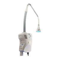
ASM, MONOBLOCK COVER WITH LASER AIMER KIT
ASM, 9 Inch Cassette Holder
Room Interface
Relay Switch
Power
<36V
Room In Use Indicator
R
I<2A
RIF Pin14
RIF Pin15
Room Interface
Relay Switch
Power<36V
Xray On Indicator
R
I<2A
RIF Pin9
RIF Pin10
Room Interface
Relay Switch
Power<36V
R
I<2A
RIF Pin4
RIF Pin5
Injector
Room Interface
RIF Pin1
RIF Pin11
AC
24V
AC Relay Core
Door Switch

 Loading...


