Brivo OEC 715/785/865 Mobile C-Arm X-Ray Product Service Manual
7-66
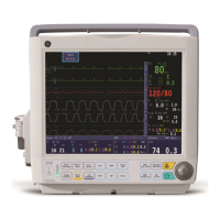
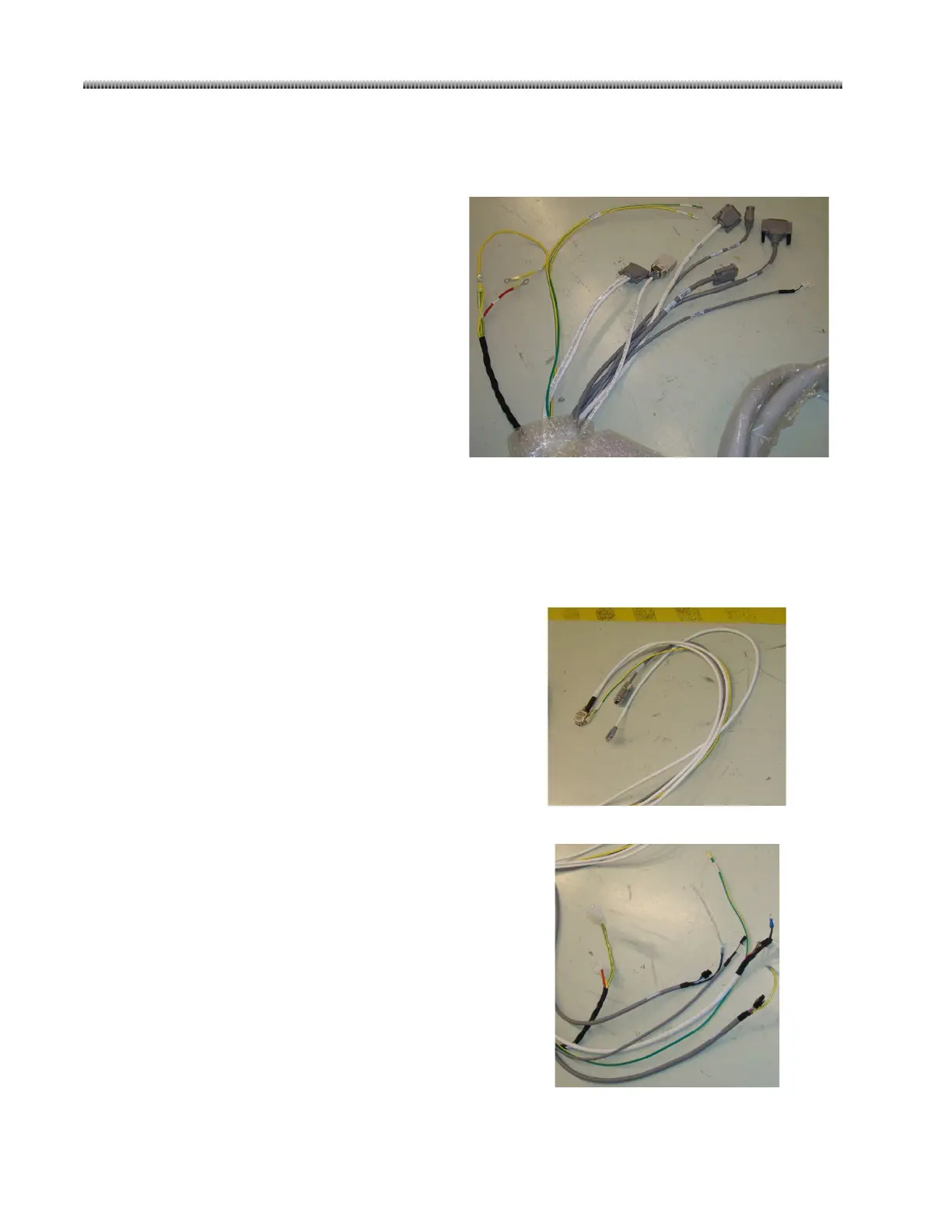
7.3.19. Bundle cable: (5075970)
Connector List (Mainframe Base Side):
Red
GND
Cap
GND
Connector List (C-arm_I.I. Side):
Connector List (C-arm_Monoblock Side):
J10
J11
Removable Filter Proximity SW
Removable Filter Proximity SW

 Loading...