System Overview
2-41
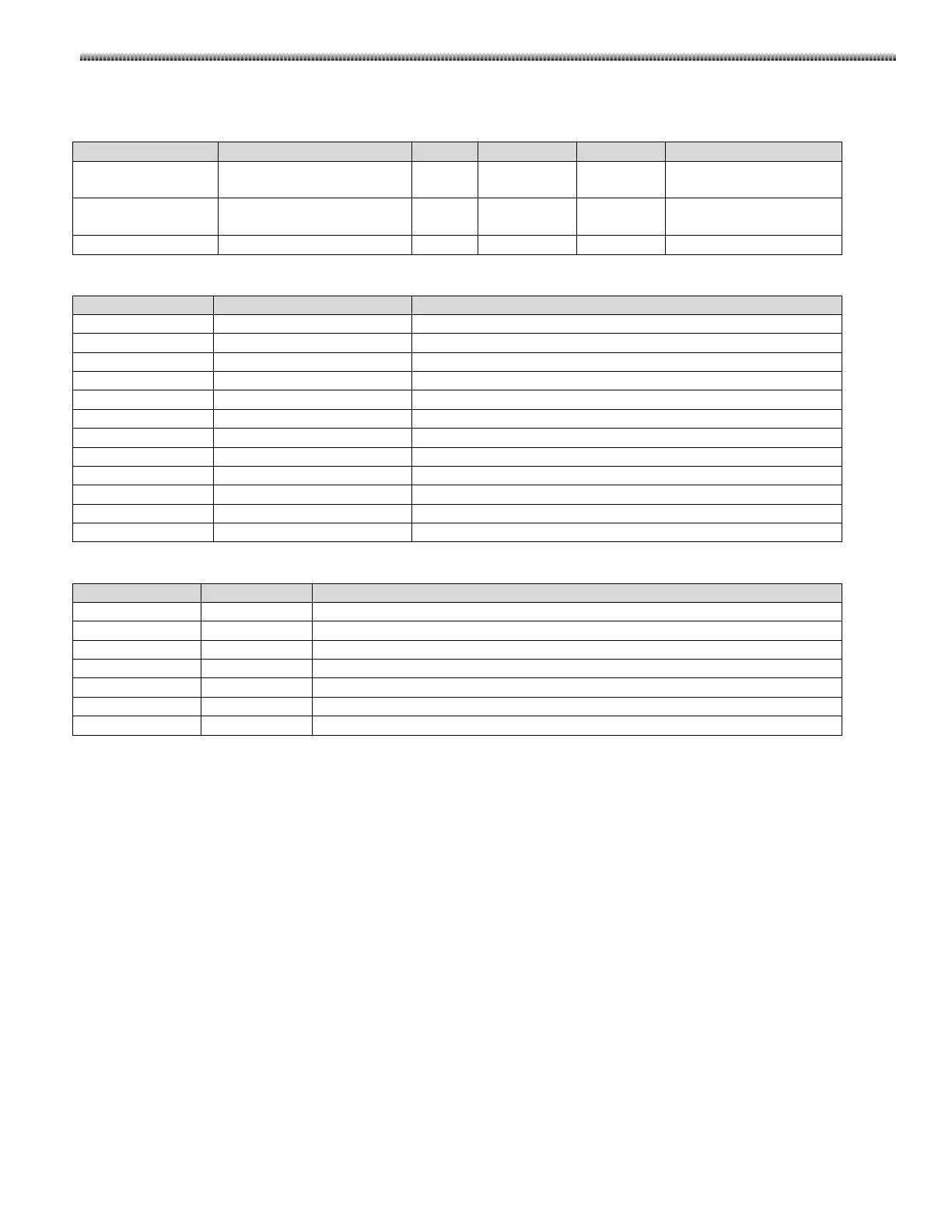
Proximity switch interface
The signals from the proximity switch are listed as follows.
DOWN_PROTECT
Proximity protecting signal
from the proximity switch.
J6-1 Digital 0V/+24V HIGH=Proximity protect
+24V_UDB
Power to the proximity
switch
J6-4 Power +24V ----
Test points list:
Proximity protect signal from proximity switch
Proximity protect signal to control relay K9
DC Voltage after rectification and regulation
LEDs list:
Light=AC input has been transformed to DC voltage
Light=up motion is enabled
Light=down motion is enabled
Light=motor current is overloaded
Light=Relay K9 is turn on and DC voltage is not applied to motor
Light=Proximity switch is in proximity protect state
Dark=signal from MCB has disabled the motor motion

 Loading...