pplication Notes
P74x/EN AP/N
1, P742, P743 (AP) 6-
Is
ol
ator
Close
d
CB
Clo
se
d
Zone
1
=
CT1
Zone
2 =
CT2
Zon
e
1
= BB1
Zon
e
2
= BB2
BB 1
CB Close
d
I
sol
a
tor Clo
sed
BB 2
Coupling Closed
CT 1 CT 2
CT 3
Check
Zon
e =
CT1
+
CT2
CT 4
VZ 3
Coupling Closed
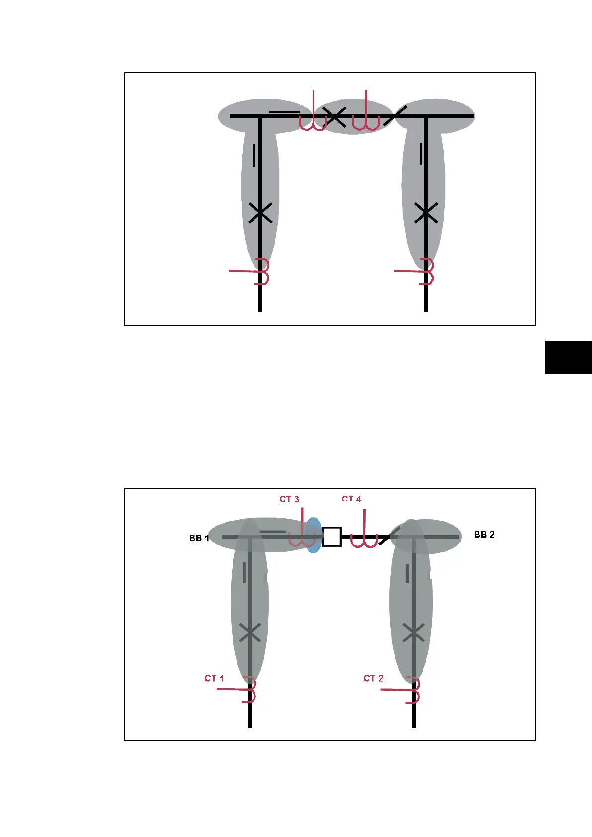
FIGURE 20: BUS COUPLER CLOSED AND ONE ISOLATOR OPEN
A zone is defined from a CT to an other CT or an open electrical element (coupler CB or
isolator).
When 2 CTs are used in the coupling and the coupler CB is closed but a coupler isolator is
open, the coupler CT (linked to that open isolator) measurement is not taken into account
and the virtual zone is extended from the coupler CT to that open coupler isolator.
There is one zone for BB1 to the coupler CT, one zone for BB2 to the open isolator and one
virtual zone from the coupler CT to the open isolator.
P0881ENa
CT 3&4 not taken into account
Coupling Open
CB Closed
CB Closed
Check Zone = CT1 + CT2
Zone 1 = CT1
Zone 2 = CT2
Zone 1 = BB1
Zone 2 = BB2
Isolator Closed
Isolator Closed
Extended
Zone
FIGURE 21: BUS COUPLER AND ONE ISOLATOR OPEN
A zone is defined from a CT to an other CT or an open electrical element (coupler CB or
isolator).