x/EN AP/Na7
-40 MiCOM P74
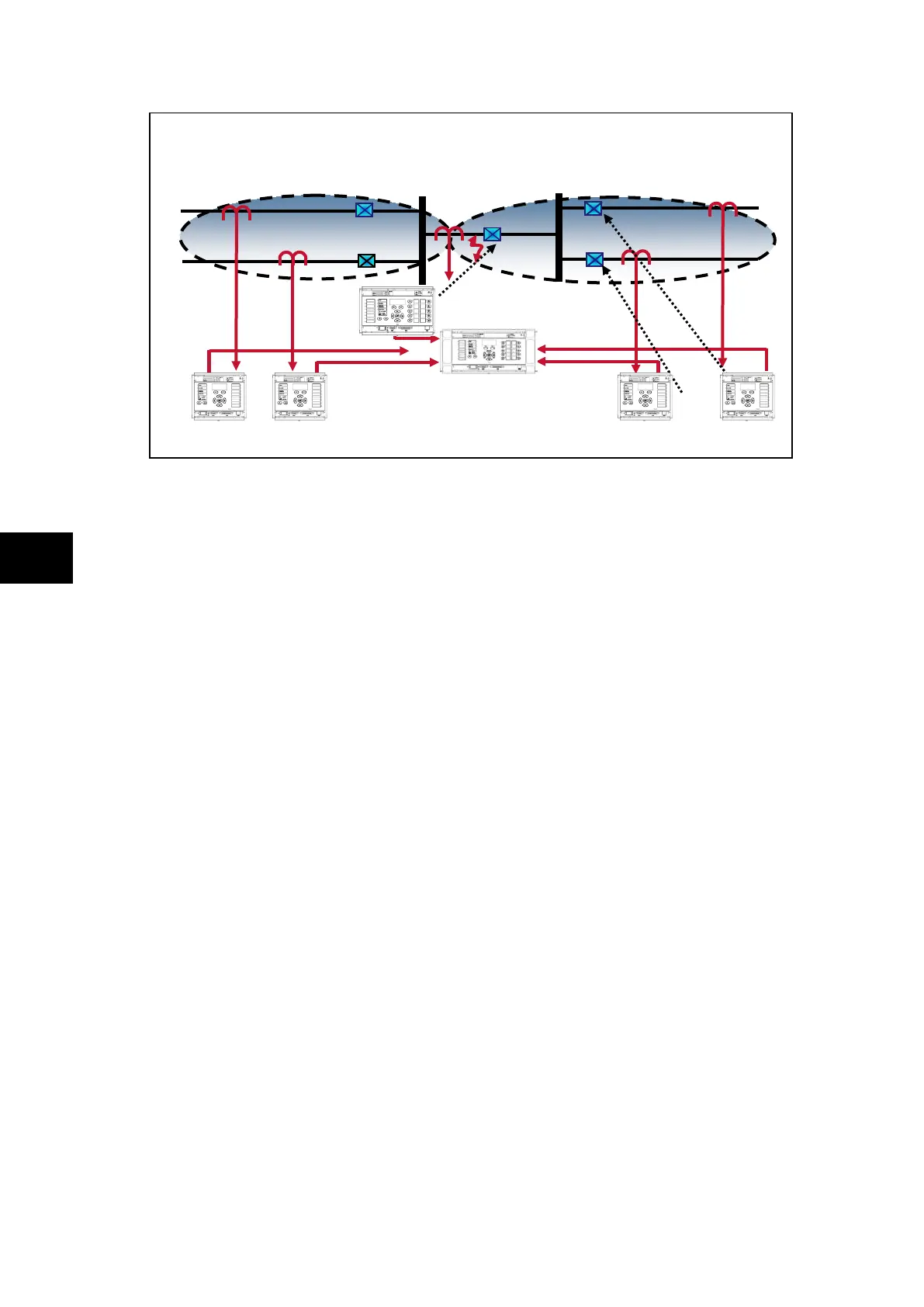
FIGURE 24: CT’S ON ONE SIDE OF BUS COUPLER,
CB CLOSED AND FAULT OCCURS BETWEEN THE CB & THE CT
Treating this as a closed bus section circuit breaker the topology algorithm will have
extended the limits of the main zones to the bus coupler CT. This then fully replicates the
scheme.
Under normal operating conditions when the circuit breaker is closed load current would flow
through the circuit breaker and differential current in the two main zones would equal zero,
as the current flowing into the zones would still equal the current flowing out.
However, if a fault occurs between the CT and the circuit breaker, the current will flow from
zone 1 into zone 2 which feeds the fault. The differential current in main zone 1 will still
equal zero, as the current flowing into the zone 1 will still equal the current flowing out, but
the differential current measured in zone 2 will be equal to that of the fault current.
In this case zone 2 would operate as will the check zone element.
Zone 1 I
diff
= I
7
+ I
8
+ I
9
= i
diff
Z1 = 0
Zone 2 I
diff
= I
9
+ I
10
+ I
11
=i
diff
Z2 = i
fault
> (I
D
>2 + k2 x I
Bias
)
Check zone I
diff
= I
7
+ I
8
+ I
10
+ I
11
= i
diff
Z2 = i
fault
> (I
D
CZ>2 + kCZ x I
Bias
)
However, when zone 2 trips the fault will still be present. The topology then analyses the
remainder of the system as follows.
1 CT Coupler with CB closed - Fault clearance -
diff
=
i
diff
feeder = i
7
+ i
8
+ i
10
+ i
11
= 0 + i