x/EN MR/Na7
Measurements and Recording
-
MiCOM P74
Menu Text Default Setting Explanation
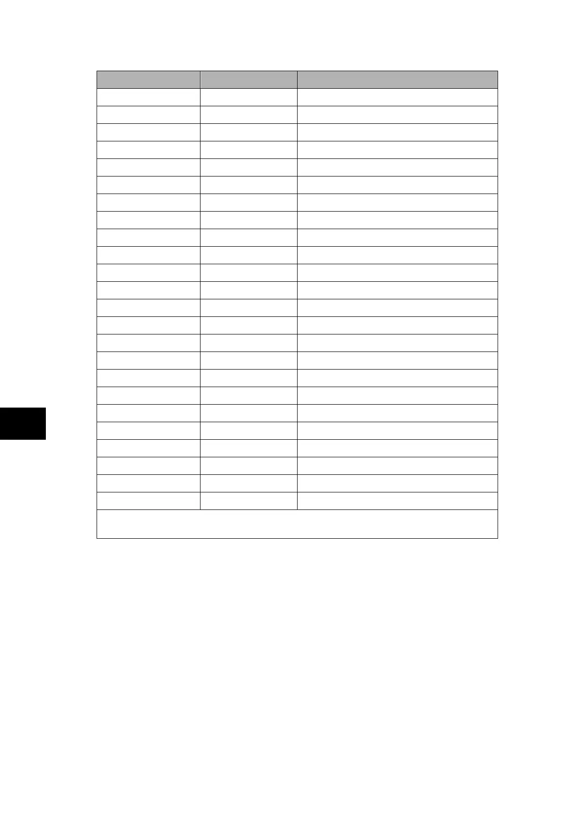
Input 12 trigger No Trigger
Digital input 13 Q2 Closed Isolator 2 closed digital channel
Input 13 trigger No Trigger
Digital input 14 Q3 Closed Isolator 3 closed digital channel
Input 14 trigger No Trigger
Digital input 15 Man. Trip zone Manual Trip of the zone digital channel
Input 15 trigger Trigger L/H
Digital input 16 Relay Label 01 Relay Label 01 digital channel
Input 16 trigger No Trigger
Digital input 17 Relay Label 02 Relay Label 02 digital channel
Input 17 trigger No Trigger
Digital input 18 Relay Label 03 Relay Label 03 digital channel
Input 18 trigger No Trigger
Digital input 19 Saturation ph A Saturation phase A digital channel
Input 19 trigger No Trigger
Digital input 20 Saturation ph B Saturation phase B digital channel
Input 20 trigger No Trigger
Digital input 21 Saturation ph C Saturation phase C digital channel
Input 21 trigger No Trigger
Digital input 22 Trip 50BF (CU) Trip 50BF from the CU digital channel
Input 22 trigger Trigger L/H
Digital input 23 Trip 87BB Trip 87BB digital channel
Input 23 trigger Trigger L/H
Digital input 24 to 32 Unused
The digital channels may be mapped to any of the opto isolated inputs or output contacts,
in addition to a number of internal relay digital signals, such as protection starts, LEDs etc.
The pre and post fault recording times are set by a combination of the "Duration" and
"Trigger Position" cells. "Duration" sets the overall recording time and the "Trigger Position"
sets the trigger point as a percentage of the duration. For example, the default settings
show that the overall recording time is set to 1.2s with the trigger point being at 33.3% of
this, giving 0.4s pre-fault and 0.8s post fault recording times.
If a further trigger occurs whilst a recording is taking place, the recorder will ignore the trigger
if the "Trigger Mode" has been set to "Single". However, if this has been set to "Extended",
the post trigger timer will be reset to zero, thereby extending the recording time.
As can be seen from the menu, each of the analog channels is selectable from the available
analog inputs to the relay. The digital channels may be mapped to any of the opto isolated
inputs or output contacts, in addition to a number of internal relay digital signals, such as
protection starts, LEDs etc. The complete list of these signals may be found by viewing the
available settings in the relay menu or via a setting file in S1. Any of the digital channels
may be selected to trigger the disturbance recorder on either a low to high or a high to low
transition, via the "Input Trigger" cell.
It is not possible to view the disturbance records locally via the LCD; they must be extracted
using suitable software such as S1. This process is fully explained in the SCADA
Communications section (P74x/EN SC).
 Loading...


