CM
When we reach the point A the Central Unit LED 8 and relay 8 will operate and when we
reach the point B the differential element will operate.
Note 1: I
D
>1 alarm timer will be set to 100s during the test.
Note 2: This test does not allow checking the slopes but only the thresholds.
If 2 currents are available:
This method will be preferred whenever possible.
Note: The 2 PUs can have different CT ratios. This must be taken into account when
injecting at the CT secondary side.
A
A
P741
Central
Unit
P742/3
Peripheral
Unit 1
P742/3
Peripheral
Unit 2
FO
FO
Test
Box
I
1
I
2
P3748ENa
FIGURE 8: CONNECTION FOR BIAS CHARACTERISTIC TESTING – CENTRALISED SOLUTION
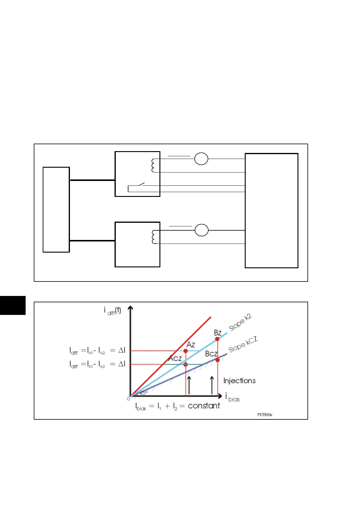
Note: The easiest way to test the thresholds is to inject an increasing slope
for I
1
and a decreasing slope for I
2
.The I
bias
= I
1
+ I
2
is thus constant
and I = I
diff
= I
2
- I
1
is increasing.
IMPORTANT: FOR THE CHECK ZONE, THE I
BIAS
INCLUDES ALL THE SUBSTATION
FEEDER CURRENTS.
To test the thresholds: