P74x/EN MT/N
1, P742, P743
(MT) 11-
REF DESCRIPTION MATERIAL
1 Assy Power Supply (24/54V)
(48/125V)
(110/250V)
ZN0021 001
ZN0021 002
ZN0021 003
2 Assy Relay Output ZN0019 001
3
Assy Opto Input
ZN0017 012
6
AssyEthernet (100Mbps) only
Assy 2
nd
rear port only
Assy Redundant Ethernet (SHR) Modulated IRIG-B
Assy Redundant Ethernet (SHR) non Modulated IRIG-B
Assy Redundant Ethernet (RSTP) Modulated IRIG-B
Assy Redundant Ethernet (RSTP) non Modulated IRIG-B
Assy Redundant Ethernet (DHS) Modulated IRIG-B
Assy Redundant Ethernet (DHS) non Modulated IRIG-B
ZN0049 001
ZN0025 002 2
nd
ZN0071 001
ZN0071 002
ZN0071 005
ZN0071 006
ZN0071 007
ZN0071 008
7
Assy Coprocessor
2070273 003
8 Communication board 2070273 001
9 Assy High break relay output ZN0042 001
23
Assy Standard Input Module
GN0010 074
24
Input Module (Univ. Inputs only)
GN0010 089
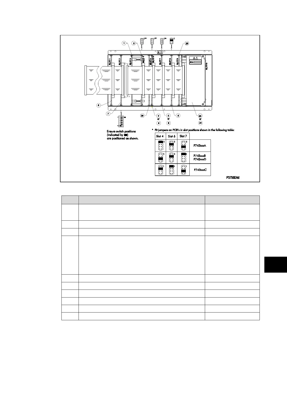
29 Assembly Screen Plate GN0058 001
FIGURE 4: P743 – PCB/MODULE LOCATIONS (VIEWED FROM FRONT)
The 64-way ribbon cable to the front panel also provides the electrical connections between
PCBs with the connections being via IDC connectors.
The slots inside the case to hold the PCBs securely in place each correspond to a rear
terminal block. Looking from the front of the relay these terminal blocks are labelled from
right to left.
Note: To ensure compatibility, always replace a faulty PCB with one of an
identical part number.