3-30
Chapter 3 Settings and Measurement
Contents General Description
Checks and Preparation
Settings and Measurement
Example of Use Specification
•
If a message window opens, follow the instruction in the message to change the setting value.
•
The Scaling function performs calculation using a ratio of the Meas. Value and EU Output Value settings.
•
The digital display shows “++++/––––” when the converted value cannot be processed by the GL860.
•
The span may be changed depending on the Scaling settings.
•
For temperature input, the offset setting for an input value is used.
Meas. Value
+5.000Upper limit
-5.000Lower limit
EU Output Value
+20.00
-20.00
Dec pt
+ xx.xx
Choose
rpm
+5 V
CH.1 10V
-5 V
+ 20.00 rpm
CH.1 Scaling 1
- 20.00 rpm
Setting example: For voltage input
Meas. Value
3°C is always added to the measurement value
22.0℃
EU Output Value
25.0℃
Setting example: For temperature input
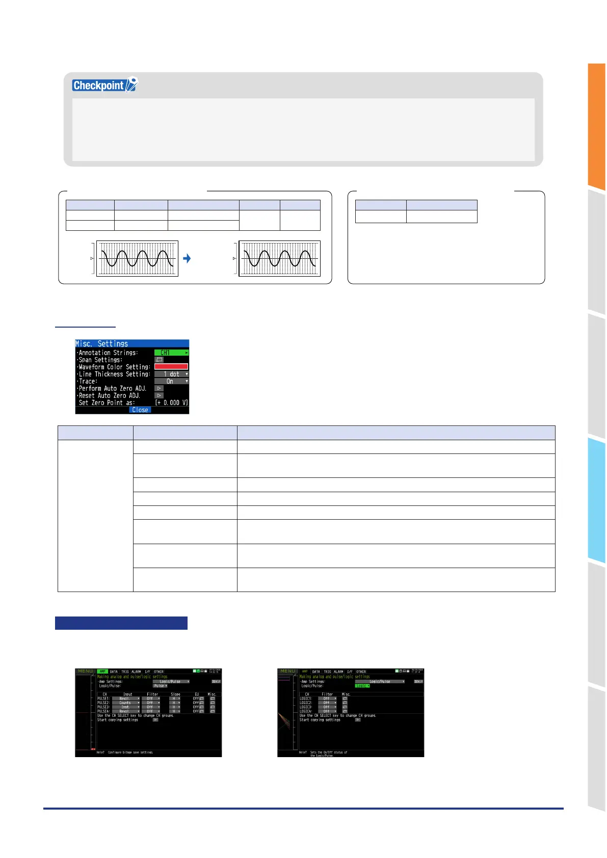
1-6. Misc.
Setting object Setting Description
Voltage, humidity Annotation Settings Set the annotation (comment) displayed in the CH.
Span Settings Set the upper and lower limits of values of a span in which a waveform should be
displayed.
Waveform Color Setting 0 to 31 for each of red, green, blue (RGB)
Line Thickness Setting Setting 1 to 8 dots
Trace This is used to set the waveform display.
Perform Auto Zero ADJ. The current input voltage is calculated as a zero-point voltage value.
The automatic adjustable voltage range is within ±10% of a set range.
Reset Auto Zero ADJ. Reset the zero-point voltage value.
* When the temperature is set, this function is not available.
Set Zero Point as: The zero-point voltage value is displayed.
* When the temperature is set, this function is not available.
Logic and Pulse settings
Makes settings related to digital input.
<For Pulse> <For Logic>