1-11
z MSTP supports mapping VLANs to Multiple Spanning Tree (MST) instances (MSTIs) by means of
a VLAN-to-instance mapping table. MSTP introduces instances (which integrates multiple VLANs
into a set) and can bind multiple VLANs to an instance, thus saving communication overhead and
improving resource utilization.
z MSTP divides a switched network into multiple regions, each containing multiple spanning trees
that are independent of one another.
z MSTP prunes a ring network into a network with tree topology, preventing packets from being
duplicated and forwarded in a network endlessly. Furthermore, it offers multiple redundant paths
for forwarding data, and thus achieves load balancing for forwarding VLAN data.
z MSTP is compatible with STP and RSTP.
Basic MSTP Terminology
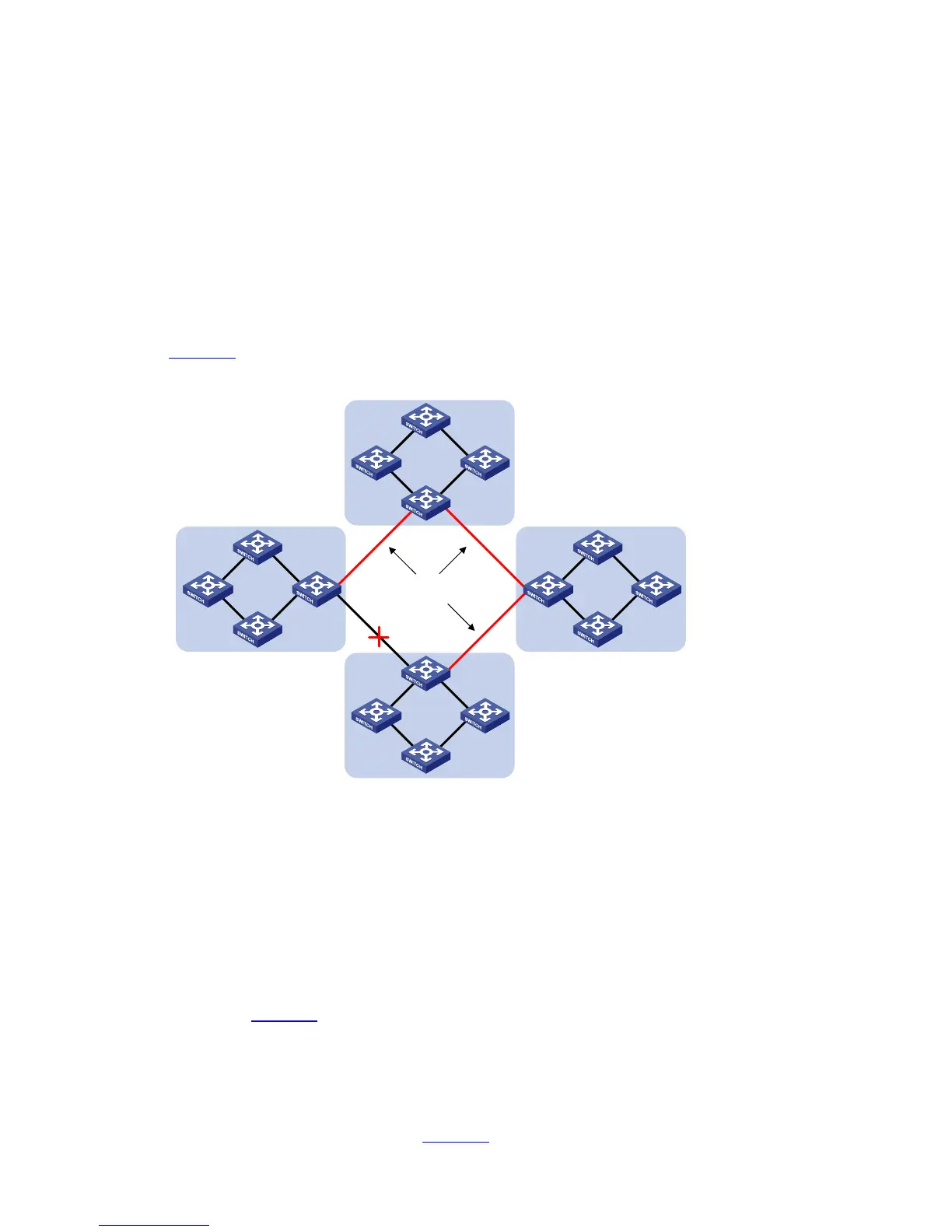
Figure 1-4 illustrates basic MSTP terms (assuming that MSTP is enabled on each switch in this figure).
Figure 1-4 Basic MSTP terminologies
CST
BPDU
Region A0:
VLAN 1 mapped to MSTI 1
VLAN 2 mapped to MSTI 2
Other VLANs mapped to CIST
BPDU BPDU
A
D
CB
Region B0:
VLAN 1 mapped to MSTI 1
VLAN 2 mapped to MSTI 2
Other VLANs mapped to CIST
Region C0:
VLAN 1 mapped to MSTI 1
VLAN 2 and 3 mapped to MSTI 2
Other VLANs mapped to CIST
Region D0:
VLAN 1 mapped to MSTI 1, B
as the regional root bridge
VLAN 2 mapped to MSTI 2, C
as the regional root bridge
Other VLANs mapped to CIST
2) MST region
A multiple spanning tree region (MST region) comprises multiple physically-interconnected
MSTP-enabled switches and the corresponding network segments connected to these switches. These
switches have the same region name, the same VLAN-to-instance mapping configuration and the same
MSTP revision level.
A switched network can contain multiple MST regions. You can group multiple switches into one MST
region by using the corresponding MSTP configuration commands.
As shown in
Figure 1-4, all the switches in region A0 are of the same MST region-related configuration,
including:
z Region name
z VLAN-to-instance mapping (that is, VLAN 1 is mapped to MSTI 1, VLAN 2 is mapped to MSTI 2,
and the other VLANs are mapped to CIST.)
z MSTP revision level (not shown in Figure 1-4)

 Loading...


