1-7
Smart Link Configuration Example
Implementing Link Redundancy Backup
Network requirements
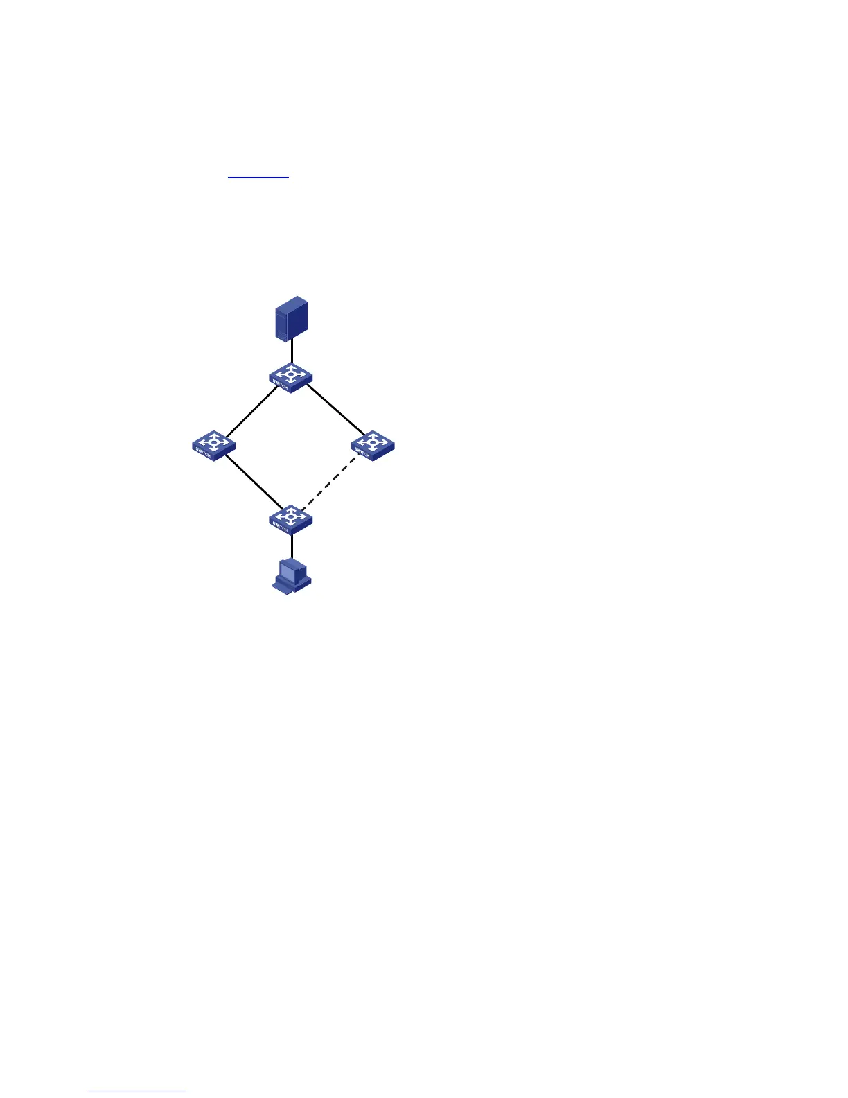
As shown in Figure 1-3, Switch A is an H3C S3100 series Ethernet switch. Switch C, Switch D and
Switch E support Smart Link. Configure Smart Link feature to provide remote PCs with reliable access
to the server.
Network diagram
Figure 1-3 Network diagram for Smart Link configuration
Switch A
Eth1/0/1 Eth1/0/2
Switch C
Server
Eth1/0/1
Eth1/0/2 Eth1/0/2
PC
Switch D
Switch E
Eth1/0/3Eth1/0/2
Eth1/0/1
Configuration procedure
1) Configure a Smart Link group on Switch A and configure member ports for it. Enable the function of
sending flush messages in Control VLAN 1.
# Enter system view.
<switchA> system-view
# Enter Ethernet port view. Disable STP on Ethernet1/0/1 and Ethernet1/0/2.
[SwitchA] interface Ethernet 1/0/1
[SwitchA-Ethernet1/0/1] stp disable
[SwitchA-Ethernet1/0/1] quit
[SwitchA] interface Ethernet 1/0/2
[SwitchA-Ethernet1/0/2] stp disable
# Return to system view.
[SwitchA-Ethernet1/0/2] quit
# Create Smart Link group 1 and enter the corresponding Smart Link group view.
[SwitchA] smart-link group 1

 Loading...


