1-47
To do... Use the command... Remarks
Display information about the root
port of the instance where the switch
reside
display stp root
Clear statistics about MSTP reset stp [ interface interface-list ] Available in user view
MSTP Configuration Example
Network requirements
Implement MSTP in the network shown in Figure 1-10 to enable packets of different VLANs to be
forwarded along different MSTIs. The detailed configurations are as follows:
z All switches in the network belong to the same MST region.
z Packets of VLAN 10, VLAN 30, VLAN 40, and VLAN 20 are forwarded along MSTI 1, MSTI 3, MSTI
4, and MSTI 0 respectively.
In this network, Switch A and Switch B operate on the convergence layer; Switch C and Switch D
operate on the access layer. VLAN 10 and VLAN 30 are limited in the convergence layer and VLAN 40
is limited in the access layer. Switch A and Switch B are configured as the root bridges of MSTI 1 and
MSTI 3 respectively. Switch C is configured as the root bridge of MSTI 4.
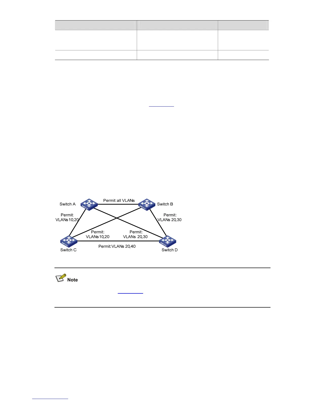
Network diagram
Figure 1-10 Network diagram for MSTP configuration
The word “permit” shown in Figure 1-10 means the corresponding link permits packets of specific
VLANs.
Configuration procedure
1) Configure Switch A
# Enter MST region view.
<Sysname> system-view
[Sysname] stp region-configuration
# Configure the region name, VLAN-to-instance mapping table, and revision level for the MST region.

 Loading...


