2-18
Configuring Multicast VLAN
Network requirements
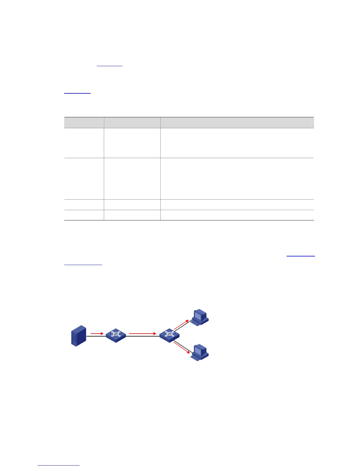
As shown in Figure 2-4, Workstation is a multicast source. Switch A forwards multicast data from the
multicast source. A Layer 2 switch, Switch B forwards the multicast data to the end users Host A and
Host B.
Table 2-21 describes the network devices involved in this example and the configurations you should
make on them.
Table 2-21 Network devices and their configurations
Device Device description Networking description
Switch A Layer 3 switch
The interface IP address of VLAN 20 is 168.10.1.1. Ethernet 1/0/1
is connected to the workstation and belongs to VLAN 20.
The interface IP address of VLAN 10 is 168.10.2.1. Ethernet 1/0/10
belongs to VLAN 10. Ethernet 1/0/10 is connected to Switch B.
Switch B Layer 2 switch
VLAN 2 contains Ethernet 1/0/1 and VLAN 3 contains Ethernet
1/0/2. The two ports are connected to Host A and Host B,
respectively.
VLAN 10 includes Ethernet 1/0/10, Ethernet1/0/1, and Ethernet
1/0/2. Ethernet 1/0/10 is connected to Switch A. VLAN 10 is a
multicast VLAN.
Host A User 1 Host A is connected to Ethernet 1/0/1 on Switch B.
Host B
User 2 Host B is connected to Ethernet 1/0/2 on Switch B.
In this configuration example, you need to configure the ports that connect Switch A and Switch B to
each other as hybrid ports. The following text describes the configuration details. You can also configure
these ports as trunk ports. The configuration procedure is omitted here. For details, see
Configuring
Multicast VLAN
.
Configure a multicast VLAN, so that users in VLAN 2 and VLAN 3 can receive multicast streams
through the multicast VLAN.
Network diagram
Figure 2-4 Network diagram for multicast VLAN configuration
WorkStation SwitchA
SwitchB
Vlan-int20
168.10.1.1
Eth1/0/1
Eth1/0/10
V
l
a
n2
V
l
an3
Eth1/0/10
Vlan10
E
th1/0/1
E
th1/0/2
HostA
HostB
Vlan-int10
168.10.2.1
Configuration procedure
The following configuration is based on the prerequisite that the devices are properly connected and all
the required IP addresses are already configured.

 Loading...


