2-5
Table 2-5 Display Monitor Link configuration
Operation Command Remarks
Display the information about
one or all Monitor Link groups
display monitor-link group
{ group-id | all }
You can use the display
command in any view.
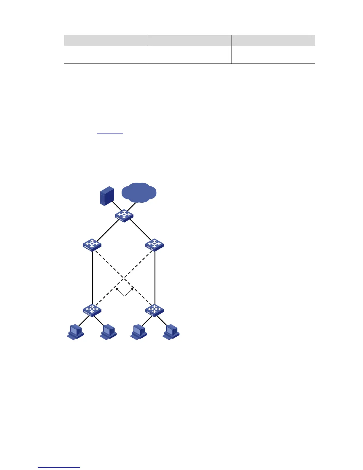
Monitor Link Configuration Example
Implementing Collaboration Between Smart Link and Monitor Link
Network requirements
As shown in Figure 2-3, the PCs access the server and Internet through the switch. Configure Smart
Link and Monitor Link to prevent the PCs from failing to access the server and Internet due to uplink link
or port failure.
Network diagram
Figure 2-3 Network diagram for Monitor Link configuration
BLOCK
Switch A Switch B
Eth1/0/1
Eth1/0/2
Switch C Switch D
Switch E
Eth1/0/1
Eth1/0/2
Eth1/0/3
Server
Eth1/0/2
Eth1/0/2
Eth1/0/1
Eth1/0/1
Eth1/0/3
Eth1/0/11Eth1/0/10
PC 1 PC 4PC 3PC 2
Internet
Configuration procedure
1) Enable Smart Link on Switch A and Switch B to implement link redundancy backup. Perform the
following configuration on Switch A. The configuration on Switch B is the same as on Switch A.
# Enter system view.
<switchA> system-view
# Enter Ethernet port view. Disable STP on Ethernet1/0/1 and Ethernet1/0/2.
[SwitchA] interface Ethernet 1/0/1

 Loading...


