1-2
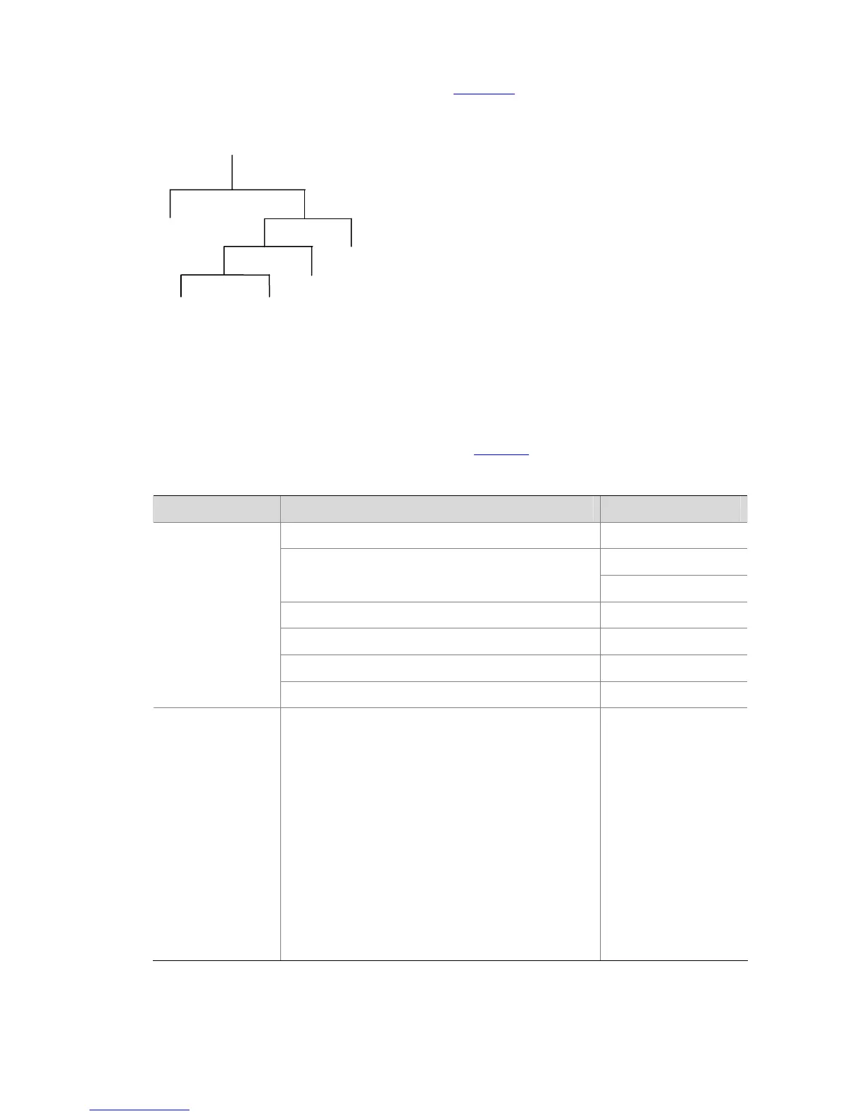
adopts a hierarchical naming scheme to organize the managed objects. It is like a tree, with each tree
node representing a managed object, as shown in
Figure 1-1. Each node in this tree can be uniquely
identified by a path starting from the root.
Figure 1-1 Architecture of the MIB tree
A
2
6
1
5
2
1
1
2
1
B
The management information base (MIB) describes the hierarchical architecture of the tree and it is the
set defined by the standard variables of the monitored network devices. In the above figure, the
managed object B can be uniquely identified by a string of numbers {1.2.1.1}. The number string is the
object identifier (OID) of the managed object.
The common MIBs supported by switches are listed in
Table 1-1.
Table 1-1 Common MIBs
MIB attribute MIB content Related RFC
MIB II based on TCP/IP network device RFC 1213
RFC 1493
BRIDGE MIB
RFC 2675
RIP MIB RFC 1724
RMON MIB RFC 2819
Ethernet MIB RFC 2665
Public MIB
IF MIB RFC 1573
Private MIB
DHCP MIB
QACL MIB
MSTP MIB
VLAN MIB
IPV6 ADDRESS MIB
MIRRORGROUP MIB
QINQ MIB
802.x MIB
HGMP MIB
NTP MIB
Device management
Interface management
—

 Loading...


