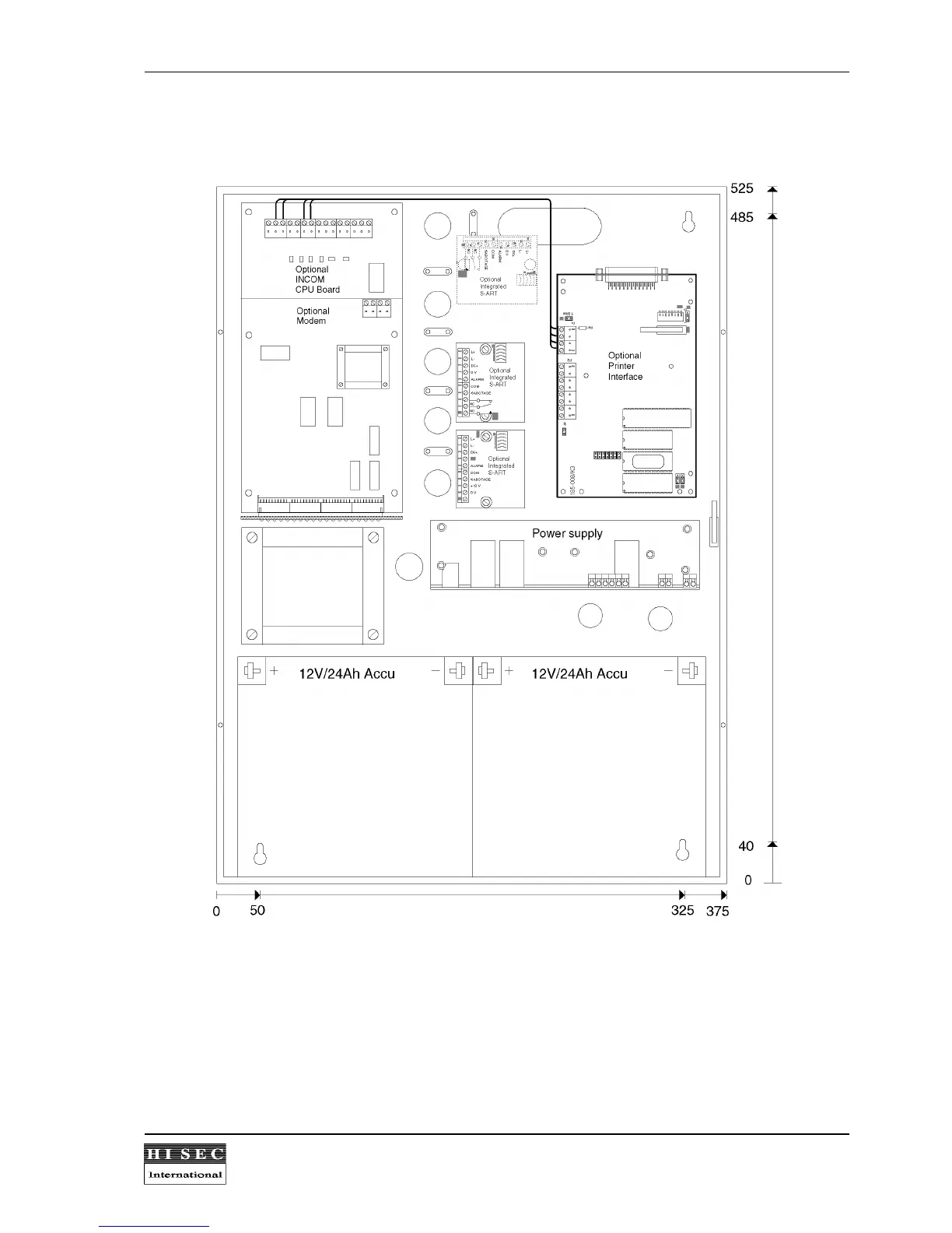
2.15 Mechanical measurement and lay-out of the power supply cabinet 90T PS.
The power supply cabinet must be mounted directly on a wall by means of the 4 "keyholes", one in each corner.
The front cover can be removed by loosening the 4 screws.
If the optional communication board is already installed it must be removed to get access to the upper-left
"keyhole". This is done by removing the 5 screws and the connected flat-cable. The central unit is then ready for
mounting. 4 M6 steel screws or corresponding wood screws must be used for this. If more cabinets are
mounted beside or on top of each other, there must always be 2 cm air space on account of the heat produced
by the central unit and also to give space for the front cover.


 To Next Page