1.3 S-ART's.
The S-ART (Serial Addressable Receiver Transmitter) is a full custom integrated circuit, developed for
transmission of data on a 2-wire cable and intended to be used to identify each individual detector in alarm or
access control systems.
Up to 15 S-ART's may be connected to a 2-wire cable. The 2 wires distributes the power supply to the S-ART's
as well as data to and from the S-ART's.
If 24V or 12V DC is needed for relays, detectors etc. this demands an extra pair of wires.
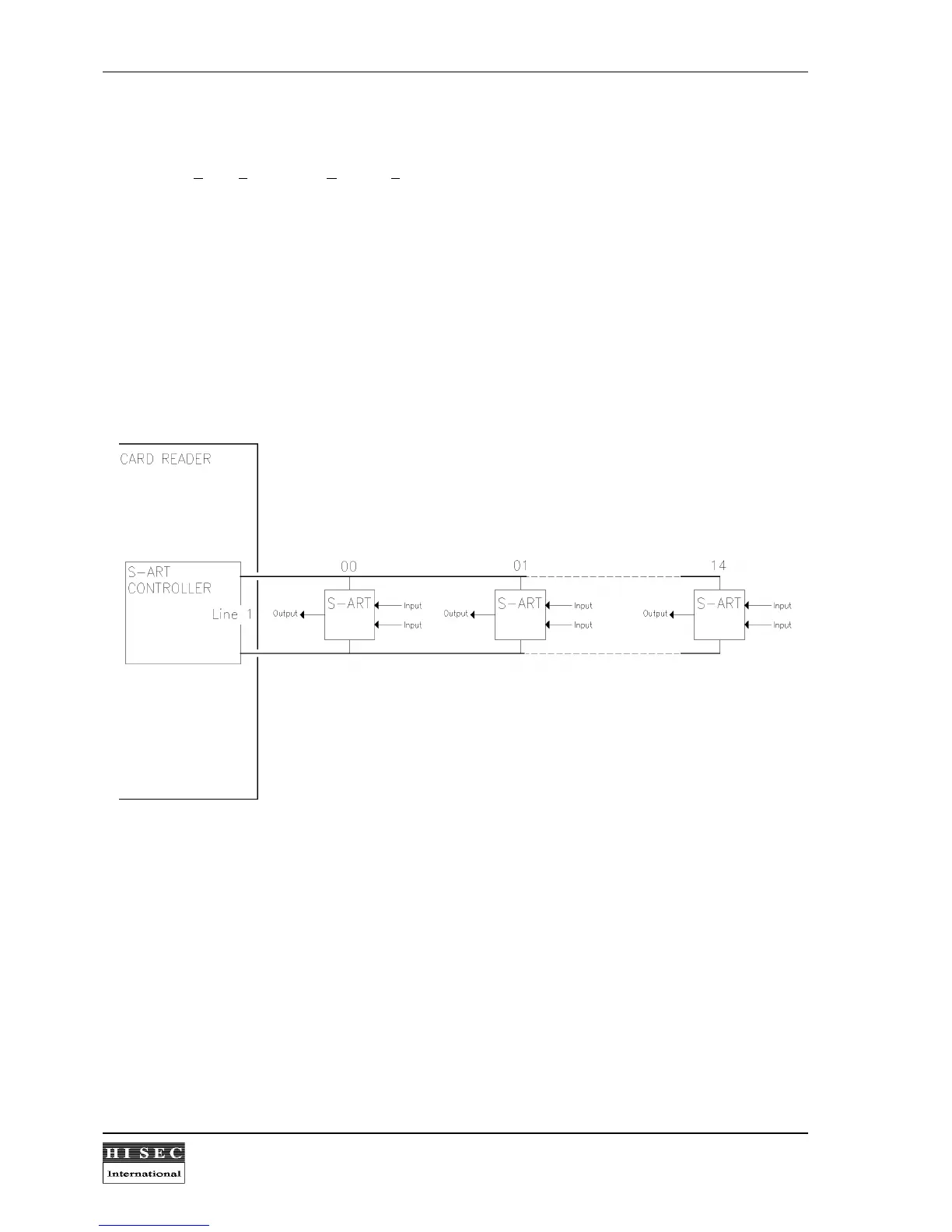
1.3.1 Block diagram.
Max. 15 S-ART-units may be connected on 1 S-ART line to the S-ART controller in the reader.
The S-ART controller, placed on the main CPU-board in the card reader, scans all the connected S-ART's and
indicates the changes of the input condition to the Main CPU when they happen. The outputs of the S-ART's are
similarly set or reset by orders from the Main CPU.
Scanning times:S-ART Address 00, 01 and 02
............. ............. ............ .............
40 to 80 mS.
S-ART Address 03 to 14
............. ............. ............ .............
130 to 260 mS.
If an S-ART output must be activated due to an event on an S-ART input there is a system reaction time.
Activation time
.. ............. ............ ............. ............ ............. ............. ............ .............
Max. 200ms.