From the above it is seen that the addresses 00, 01 and 02 will always give the quickest possible overall reaction
time and it is therefore recommended to use these addresses for exit push buttons and electric striking plates.
The scanning signals on the bus are explained in details in the next section.
1.3.2 Line signals.
The S-ART transmission includes 10 bits.
5 Address bits
1 Address parity bit
1 Read/write bit
2 Data bits
1 Data parity bit
When an S-ART recognizes its own address, it reacts corresponding to the read/write bit like this:
1. Data for the two outputs (OUT 0 and OUT 1) are latched.
2. Data of the two inputs (IN 0 and IN 1) are transferred to the S-ART controller.
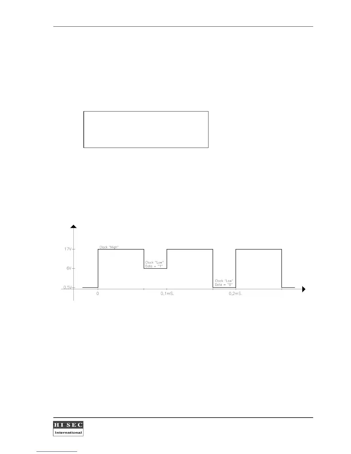
The line signal is divided into 3 levels in order to transmit DATA as well as CLOCK.
When the clock is high (17V), all S-ART's are power supplied by the S-ART controller via a transistor.
When the clock is low, data are transmitted. Logical "1" is 6.2V (supplied by the S-ART controller) and logical "0"
is 0V.
When the S-ART has recognized its address and is ready to transmit input data to the S-ART controller, it
makes a short circuit of the line via 150 ohm in case of a logical "0" and stays in the high impedance state in
case of a logical "1", thus maintaining the 6.2V of the S-ART controller.