When fixing the back plate, it must be taken into consideration that the cover takes app. 3 mm extra space on all
sides as shown on the drawing of the back-plate. Also to dismount the unit it is necessary with app. 2 cm of free
space above the unit.
The recommended mounting height of the panels is app. 150 - 155 cm, to the upper edge of the cabinet.
Technical data
Stock number:
Magstripe Card readers
.... ........ .......... .......... .......... ..........
90T RKP ACM
Wiegand Card reader
........ ........ .......... .......... .......... ..........
90T RKP ACW
Supply voltage
........ .......... .......... ........ .......... .......... .......... ..........
10V - 30V DC
Current consumption
......... .......... ........ .......... .......... .......... ..........
90mA/24VDC + Typ. 60mA with backlight on
Cable Length: RS485 bus
... ........ .......... .......... .......... ..........
Max. 1000m - shielded, twisted pair.
S-ART bus
... ........ .......... .......... .......... ..........
Max. 500m - unshielded, twisted pair.
.......... ........ .......... .......... .......... ..........
Max. 250m - shielded, twisted pair.
Temperature range
.......... .......... ........ .......... .......... .......... ..........
0 - 55
0
C
2.3.2 Address switch setting in the Card reader.
4 switches are used to programme the address of each unit on the bus. The switches are placed on the CPU-
board of the Card reader.
The addresses are set binary from 00 to 31. In systems
with
THOR intrusion integration address 00 cannot be
used by a Card reader. In a multi-reader system
without
integration one of the readers
must
be programmed
as address 00, as this address automatic will work as the master for the multi-master protocol.
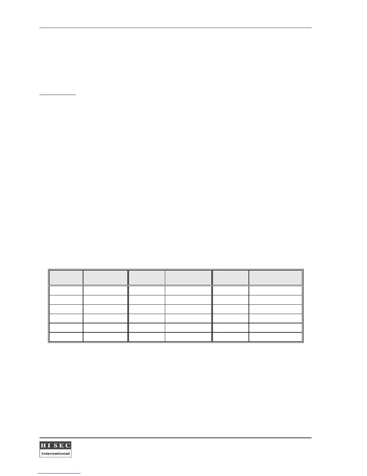
Address Switch setting
4321
Address Switch setting
4321
Address Switch setting
4321
00/16 0000 01/17 0001 02/18 0010
03/19 0011 04/20 0100 05/21 0101
06/22 0110 07/23 0111 08/24 1000
09/25 1001 10/26 1010 11/27 1011
12/28 1100 13/29 1101 14/30 1110
15/31 1111
0 means the switch is in the ON position, and 1 means the switch is in the OFF position. Please note the
ON/OFF position marked on the switch.
The address range 0-15 or 16-31 is selected by the option bit 8 during the initialization of the reader.
Please note:
One jumper connecting the small back-up battery on the CPU-board to the RAM memory must
be in the ON position in the card reader. If it is in the off position the programming will be lost in case of
power off.