4. Remove the display from the CPU board by unscrewing the 4 screws fixing the display.
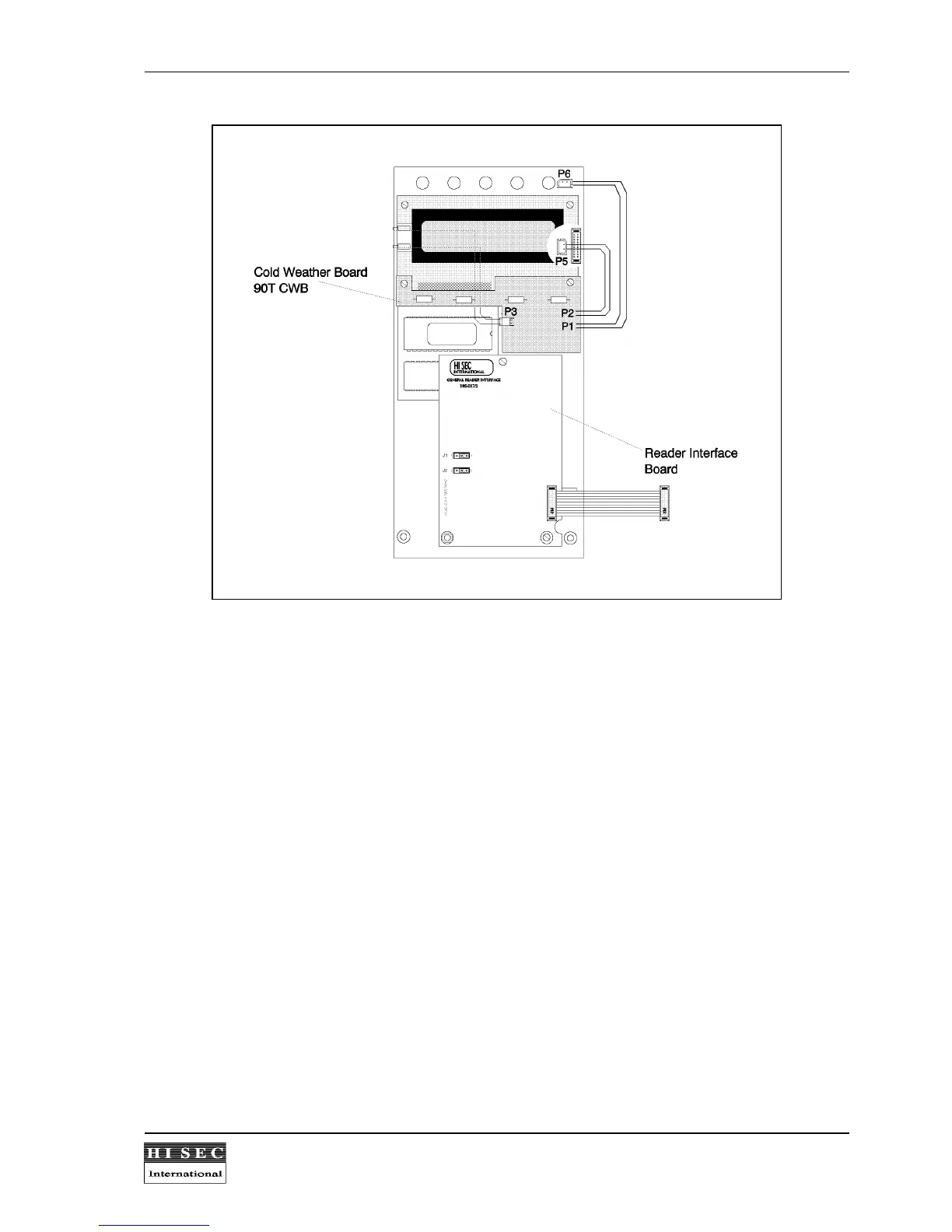
5. Connect the plug coming from the display board to the P3 connector on the 90T CWB board.
6. Connect the P2 plug coming from the 90T CWB board to the P5 connector on the CPU-board.
7. Connect the P1 plug coming from the 90T CWB board to the P6 connector on the CPU-board.
8. Mount the display and the cold weather board on the CPU board. The 90T CWB must be placed on top of
the display board using the existing screws.
Technical Specification:
Temperature range
....... ............. .......................... ............. ..................................................
- 25
0
C /24V DC
............ ............. .......................... ............. ..................................................
- 15
0
C /12V DC
Power consumption
...... ............. .......................... ............. ..................................................
max 500 mA (heating
............ ............. .......................... ............. ..................................................
element on) /24V DC
............ ............. .......................... ............. ..................................................
(incl. terminal
............ ............. .......................... ............. ..................................................
consumption).