The controllers are configured from the factory with the set-up to be used by the THOR system meaning that no
jumpers, switches or potentiometers should be changed. Only the potentiometers RV3 and RV4 can be adjusted
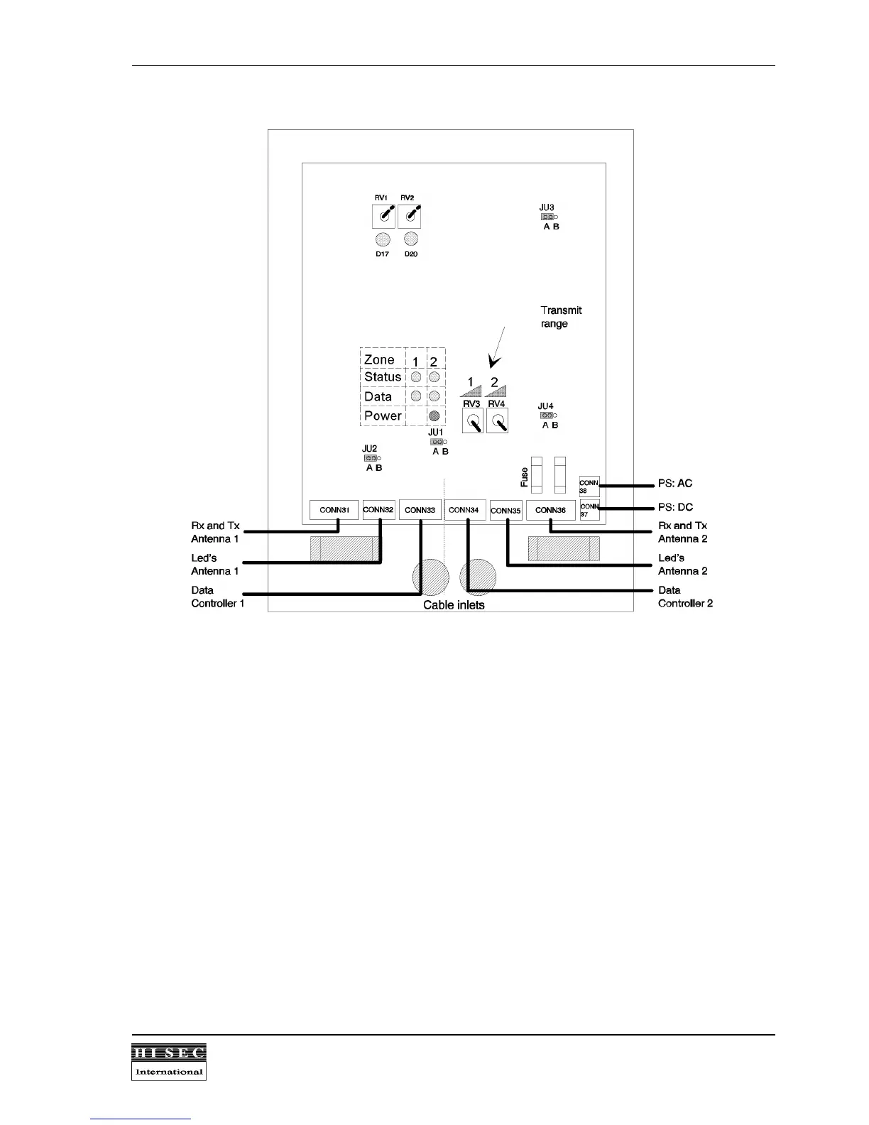
to reduce the antenna range if needed. The potentiometers are default set for maximum range.
LED indicators:
D17
and
D20
: (yellow) Rx zone 1 and 2 will indicate (flicker), when a card is in the detection range of the
antenna.
Status:
(yellow) Will flash from 1 to 15 times during the power-up reset. The diode will also flicker, if the
back ground noise in the vicinity of the antenna is too great for the system to be able to read cards at
the normal range.
Data
: (yellow) Will flicker, when a card is accepted by the controller and send to the ERC terminal.
Power:
(green) flicker to indicate that the polling has started.