4 Electrical and control settings
Unit electrical wiring and connection
SMGB0099 rev.0 - 12/2016
155
4
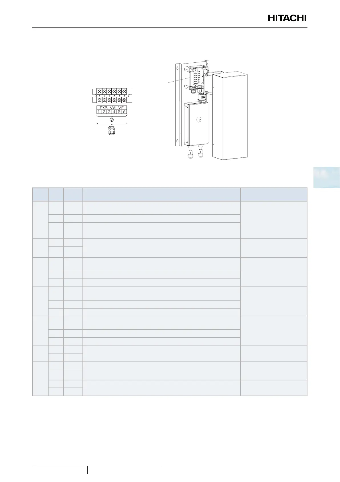
Expansion valve box terminal board
DX-Interface EXV-(2.0-10.0)E2
.valve
x
Expansion
valve box
Terminal board connections and remarks
Terminal board 1
Mark Item Name Description
Wire and maximum current
specication (EN60335-1)
1 V+
DUTY V: Duty control by voltage (0~10V) (0~5V) (optional):
V+: Output power to device (+24Vdc)
Wire section: 3x0,5mm
2
? NOTE
Maximum power by 24Vdc
output: 3 W
2 D D: Voltage input (0~10V) (0~5V)
3 N N: GND
4 1
CO
2
signal (optional):
Free contact: By closing the signal, the fan speed is set to High mode.
Wire section: 2x0,5mm
2
5 2
6 T
EC1: PWM Output control for EC FAN 1 (optional):
T: Tach input signal (Hz)
Wire section: 3x0,5mm
2
(*1)
7 P P: PWM output signal (0-100%)
8 G G: GND
9 T
EC2: PWM Output control for EC FAN 2 (optional):
T: Tach input signal (Hz)
Wire section: 3x0,5mm
2
(*1)
10 P P: PWM output signal (0-100%)
11 G G: GND
12 V+
DUTY A: Duty control by current (4~20mA) (optional):
V+: Output power to device (+24Vdc)
Wire section: 3x0,5mm
2
NOTE: Maximum power by
24Vdc output: 3 W
13 D D: Current input (4~20mA)
14 N N: GND
15 1
FS: Float switch (optional):
Free contact between terminals 1(15) and 2(16)
Wire section: 2x0,5mm
2
16 2
17 1 CONTROL: H-LINK and remote controller communication (Necessary):
The H-LINK transmission between outdoor unit and indoor unit is 2 wired to
terminals 1-2.
Wire section: 2x0,5mm
2
18 2
19 A
The Remote controller must be connected between pins A and B
(non polarity)
Wire section: 2x0,5mm
2
20 B
? NOTE
(*1): If fan wiring length is higher than 3m, use shielded wires in compliance with local codes.
 Loading...


