4 Electrical and control settings
Unit electrical wiring and connection
SMGB0099 rev.0 - 12/2016
156
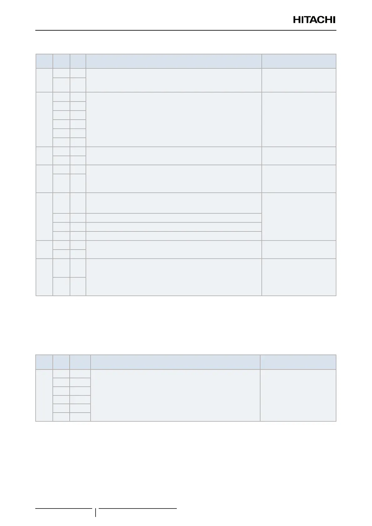
Terminal board 2
Mark Item Name Description
Wire and maximum current
specication (EN60335-1)
1
L1
P.S.: Power supply (necessary):
The main power supply connection (230 Vac) is wired to terminals L1 and N.
1~ 230V 50Hz, Max current. 5A
Wire section: 3x0,75mm
2
2
N
3
1
EXP. VALVE: Expansion valve connection (necessary):
Link to expansion valve assembly. Number links from 1 to 6 must match in
e-box terminal board and expansion valve terminal board
Wire section: 6x0,5mm
2
4
2
5
3
6
4
7
5
8
6
-
9
-
Not used -
10
-
11
L
MD: Motor Drain discharge (optional):
A drain water pump (eld supplied) can be connected to DX-kit interface.
1~ 230V 50Hz Max current:
1A (output)
Wire section: 2x0,75mm
2
12
N
13
N
FAN CONTROL: Fan tap speed control by HITACHI remote controller
(optional):
N-Neutral phase connection (common)
Maximum current allowed: 3,5A
Wire section: 4x0,75mm
2
(*1)
14
H H: High fan speed signal
15
M M: Medium fan speed signal
16
L L: Low fan speed signal
-
17
-
Not used -
18
-
19
1
M. AL: Motor alarm signal:
Alarm input signal can be used for alarm link between the DX-Kit interface
and the unit connected. If the jumper between terminal 1 (19) and 2 (20) is
open, unit will be switched to alarm condition. Connect again to restart the
system
Wire section: 2x0,75mm
2
(*2)
20
2
? NOTE
• (*1): Locked rotor amperage (LRA) must be lower than 8A.
• (*2): Alarm signal with high power (1~ 230V 50Hz): In case of M. Al, connection is not necessary. The harness jumper provided inside
the DX-Interface must be used.
Expansion valve box
Mark Item Name Description
Wire and maximum current
specication (EN60335-1)
1 1
Control connection (necessary):
Link to control assembly. Number links from 1 to 6 must match in
expansion valve terminal board and control terminal board.
Wire section: 6x0,5mm
2
2 2
3 3
4 4
5 5
6 6
 Loading...


