4 Electrical and control settings
Wiring diagrams for indoor units and complementary systems
SMGB0099 rev.0 - 12/2016
175
4
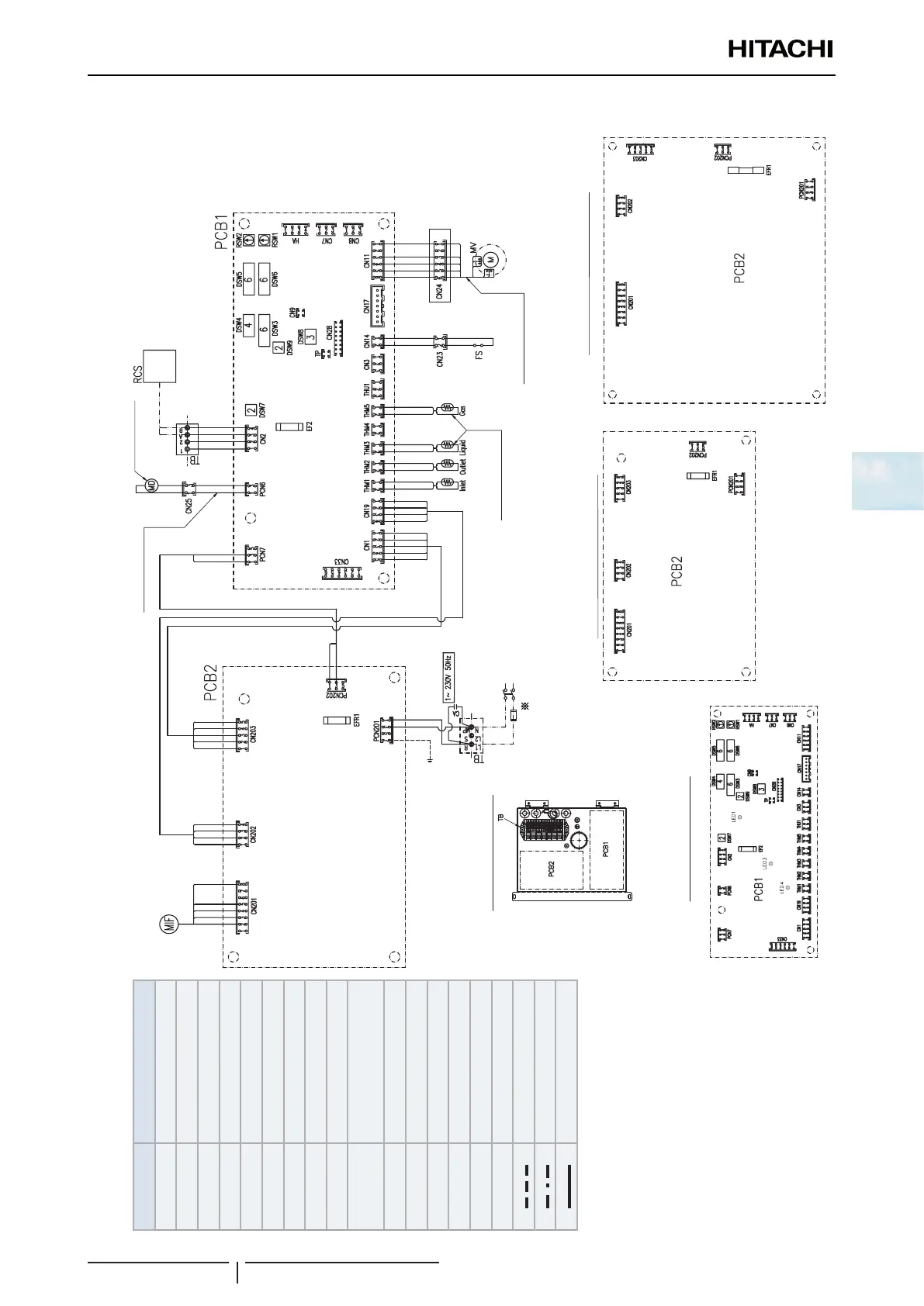
Wiring diagrams for the RPI(M)-(0.6-6.0)FSN4E indoor units
PCB1 sockets location
For RPI-(0.6-2.0)FSN4E
For RPI-(2.5-6.0)FSN4E
Expansion valve coil
comes from Evap. unit
Liquid and gas THM come
from evaporator unit
Electrical box
Drain pump assy
(Only for -DU models)
Only for:
- DU models
- Drain pump kit
RPIM
only
Mark Name
CA Capacitor
CN23, 25 Aerial connector
DSW3~9 Dip switch for settings
RSW1, 2 Rotary switch
EF2 Fuse
EFR1 Fuse
FS Float switch
MD Drain pump
MIF Motor for Indoor fan
MV
Micro-computer control
expansion valve
LED1, 3, 4, 6 Alarm code
PCB1, 2 Printed circuit board
RCS Remote control switch
TB Terminal board
THM1~5 Thermistors
◆
Field supplied
Field wiring
Earth wiring
Factory wiring

 Loading...


