4 Electrical and control settings
Wiring diagrams for indoor units and complementary systems
SMGB0099 rev.0 - 12/2016
176
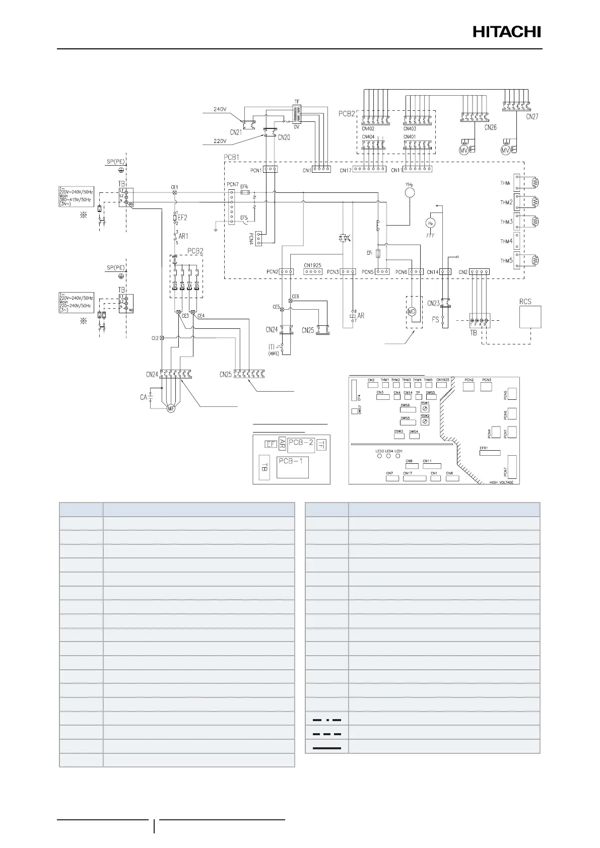
Wiring diagrams for the RPI-(8.0/10.0)FSN3E(-f) indoor units
Mark Name
AR Auxiliary relay
CA Capacitor for Indoor fan
CN
20~n
Connector
DSW
3
Unit capacity code
DSW
4
Unit model code
DSW
5
Refrigerant cycle nº
DSW
6
Indoor unit setting
DSW
7
Fuse recover/Remote control selector
EF2 Fuse
EFR1 Fuse
FS Float switch
ITI Internal thermostat for Indoor unit fan
MD Motor for drain discharge mechanism
MIF Motor for Indoor fan
MV Expansion valve
LED
1~3
Alarm code
PCB1 Main printed circuit board
PCB2 Relay printed circuit board
Mark Name
RCS Remote control switch
RSW
1
Indoor unit nº settings
RSW
2
Refrigerant cycle nº
TB Terminal board
TF Transformer
THM
1
Inlet air thermistor
THM
2
Outlet air thermistor
THM
3
Liquid pipe thermistor
THM
5
Gas pipe thermistor
X2 High speed terminal
X3 Medium speed terminal
X4 Low speed terminal
X5 S-Low speed terminal
Field supplied
Field wiring
Earth wiring
Factory wiring
Main
switch
LSP connector
(Factory supplied)
HSP connector
PCB sockets location
(Option)
Electrical control box
for Indoor unit
Main
switch
Air inlet
Alarm
Air outlet
Liquid pipe
Gas pipe
For
For

 Loading...


